- ページ 12
スイッチ Cisco 300 SeriesのPDF クイック・スタート・マニュアルをオンラインで閲覧またはダウンロードできます。Cisco 300 Series 18 ページ。 Managed switches
Cisco 300 Series にも: データシート (14 ページ), クイック・スタート・マニュアル (17 ページ), クイック・スタート・マニュアル (17 ページ)

- 1. Quick Start Guide
- 2. Mounting the Cisco Switch
- 3. Rack-Mount Placement
- 4. Wall Mounting
- 5. Connecting Network Devices
- 6. Power over Ethernet (Poe) Considerations
- 7. Troubleshoot Your Connection
- 8. Front Panel Ports
- 9. Reset Button
- 10. Back Panel
- 11. Front Panel Leds
- 12. Returning the Device to the Factory Default Settings
- 13. Where to Go from here
Features of the Cisco 300 Series Managed
4
Switch
This section describes the exterior of the managed switches including
ports, LEDs, and connections.
Front Panel Ports
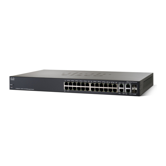
The ports and LEDs are located on the front panel of the switch.
LINK
ACT
GIGABIT
1
System
Reset
SG300-10SFP 10-Port Gigabit Managed SFP Switch
RJ-45 Ethernet Ports—Use these ports to connect network devices, such
as computers, printers, and access points, to the switch.
SFP (if present)—The small form-factor pluggable (SFP) ports are
connection points for modules, so the switch can link to other switches.
These ports are also commonly referred to as miniGigaBit Interface
Converter (miniGBIC) ports. The term SFP will be used in this guide.
• SFP ports are compatible with Cisco modules MGBT1, MGBSX1,
MGBLH1, MGBLX1, MGBBX1, MFELX1, MFEFX1, MFEBX1, and MGBT1, as
well as other brands of modules.
• Some SFP interfaces are shared with one other RJ-45 port, called a
combo port. When the SFP is active, the adjacent RJ-45 port is
disabled. Combo ports are indicated by the presence of a bar on the
panel that connects them, as shown in the following example:
12
2
3
4
5
LINK/ACT GIGABIT
G3
G4
miniGBIC
LINK/ACT
6
7
8
G9
LINK/ACT
GIGABIT
G9
SFP
Cisco 300 Series Managed Switches
CISCO Small Business
GIGABIT
LINK/ACT
GIGABIT
SFP
G10
SFP
