会議システム Crestron UC-M130-TのPDF クイックスタートをオンラインで閲覧またはダウンロードできます。Crestron UC-M130-T 2 ページ。 Flex tabletop uc video conference system for microsoft teams rooms
Crestron UC-M130-T にも: クイック・スタート・マニュアル (9 ページ)
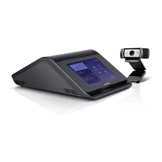
UC-M130-T
Crestron Flex M130 Tabletop UC Video Conference System for Microsoft Teams™
The Crestron® UC-M130-T Tabletop UC Video Conference System for Microsoft Teams™
delivers a powerful, professional solution for knowledge workers who want the Microsoft Teams
software experience in small to midsize meeting and conference rooms.
To use the UC-M130-T system you must have the following:
•
A Microsoft Teams or Skype® for Business software account
•
An environment running Microsoft Exchange (2013 SP1 or later for on-premises installation
or M365 for cloud) for scheduling and/or Skype for Business 2015 (on-premises installation
or M365 for cloud)
U C
- B R
U C
K T
E N
- 1 0
G I N
0
E
H D
U S
B 2
. 0
C C
C A
T 5
e
Check the Box
Item
UC-M130-T
CBL-CAT5E-7, 7 ft (2.1 m) CAT5e Cable (P/N 6509924)
CBL-USB-A-EXT-15, 15 ft (4.57 m) USB Extension Cable, Type A Male-to-Female,
(P/N 6508260)
CCS-CAM-USB-F-100 Logitech
Webcam C930e (P/N 6506442)
®
CCS-UC-1-T-V, Crestron Mercury
Tabletop UC Conference Console for Microsoft
®
Teams (P/N 6510716)
PW-2420RU, Desktop Power Pack, 24VDC, 2.5A (P/N 6500187)
UC-BRKT-100-ASSY Wall Bracket Assembly (includes HD-CONV-USB-200,
CBL-MDP-HD-0.5, UC-CONN-HD, and UC-ENGINE, Connector Cover Screws with
Tools, and Mounting Hardware) (P/N 6510636)
NOTE:
Your system will be provided with the UC-ENGINE mounted on the UC-BRKT-100-ASSY.
Future packages will include the UC-ENGINE-SD mounted on the UC-BRKT-100-SD-ASSY.
Additional Requirements
The following items (not included) are required to build the system.
•
A video display, connected to the UC-ENGINE
•
USB keyboard and mouse to configure the system
•
HDMI® cable to connect a display device
•
HDMI cable to connect an HDMI source
•
Ethernet cable to connect the PoE injector to the network
•
#1 Phillips screwdriver
•
Drill with a 5/16 in. bit (required for use with mounting anchors)
NOTE:
Crestron recommends using Crestron cables only. For optimum performance, Crestron
offers the UC-M-ACCY KIT which includes all of the required hookup cables and a wireless
keyboard with integrated touchpad.
Optional Items
D i s
The following can be added to a Flex system.
p l a
y
•
CCS-UCA-SMK Swivel Mount Kit
•
CCS-UCA-MIC Microphone Pods
M I
Install the Wall Bracket Assembly
The wall bracket assembly can be installed on a wall behind a display device, or attached to
the rear of the display device. The wall bracket assembly includes mounting slots on both side
S
C A
edges, spaced 100, 200, and 300 mm vertically, to allow for attachment to either side of the
M
display mounting plate. Additional mounting holes are provided on each side for other mounting
U S
B
locations. Centerline mounting holes are also provided for attachment to the building structure.
F 1
Integrated, reusable cable tie wraps manage cable runs between the wall bracket and peripheral
0 0
devices.
Dimensions and Callouts
16.00 in.
Qty
(406 mm)
1
1
1
1
1
15.44 in.
(392 mm)
1
1
NOTES:
•
The integrated cable tie wraps are reusable. Take care to avoid damage to the cable tie
wraps.
14.00 in.
(356 mm)
13.45 in.
(342 mm)
7.00 in.
(178 mm)
Reusable Cable Tie Wrap (x4)
Connector Cover
HD-CONV-USB-200
UC-ENGINE
6.70 in.
(170 mm)
Connector Cover
Wall Plate Opening
Power Pack
5.00 in.
(127 mm)
13.42 in.
(341 mm)
•
The wall bracket assembly has an opening and pass through screw holes for placement
over a US electrical wall box that can be covered by a decorative wall plate. If the wall
plate opening will be positioned over an electrical wall box, longer screws will be needed
to secure the decorative wall plate to the electrical box. Do not secure the wall bracket
assembly with the wall plate opening screws.
When mounting on a wall, the wall bracket assembly should be anchored to the wall. The screws
and anchors included with the assembly are best suited for surfaces with 3/8 in. to 3/4 in.
thickness. To use the included anchors, perform the following procedure.
1.
Drill a 5/16 in. pilot hole.
2.
Fold the anchor in the middle and pinch
the ends together.
3.
Insert the anchor in the hole and tap flush
with the wall.
Install the Wall Bracket Assembly On a Wall
14.92 in.
(378 mm)
Quick Start
4.
Insert the included anchor key to pop the
anchor open and lock it.
WARNING:
Do not force or hammer key.
5.
Drive the screw partially into the anchor,
leaving 1/4 in. of the screw exposed.
6.
Repeat steps 1 - 5 for the other anchor.
7.
Place the wall bracket assembly on the
screws and hand tighten the screws until
the wall bracket is secured to the wall.