レシーバー Crestron DigitalMedia 8G+ DM-RMC-4K-100-C-1GのPDF マニュアルよりをオンラインで閲覧またはダウンロードできます。Crestron DigitalMedia 8G+ DM-RMC-4K-100-C-1G 2 ページ。 Wall plate 4k receiver and room controller 100
Crestron DigitalMedia 8G+ DM-RMC-4K-100-C-1G にも: 補足マニュアル (12 ページ)
DO
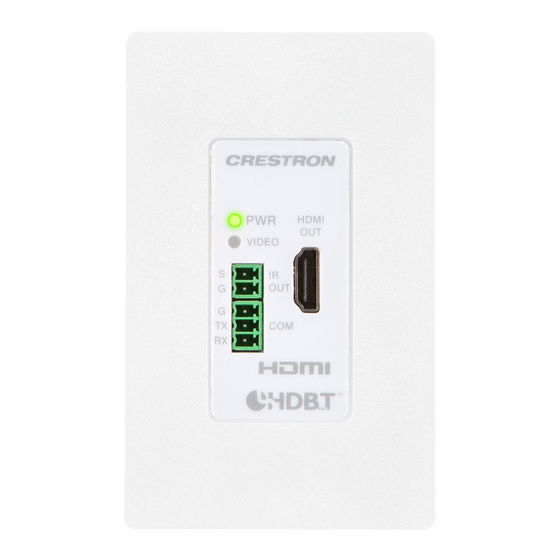
DM-RMC-4K-100-C-1G
Wall Plate 4K DigitalMedia 8G+
and Room Controller 100
DO
Make Connections to the Rear Panel
Make connections to the rear panel of the DM-RMC-4K-100-C-1G before mounting the unit into
an electrical box. If the unit is to be mounted under a table or onto a flat surface or rack rail, make
connections to the rear panel after the unit is mounted. (For mounting instructions, refer to the
"DO Install the Device" section.)
Make connections to the rear panel as follows:
DM IN: Connect to the DM 8G+
output of a DigitalMedia™ switcher, DigitalMedia 8G+
®
or other DigitalMedia device or to an HDBaseT
DM IN Wiring
PIN
Pin 1
WIRE COLOR
NUM.
Pin 8
1
Orange/White
2
Orange
3
Green/White
4
Blue
NOTE:
The DM IN port is a PoDM powered device (PD) port and is also compatible with HDBaseT
PoE. In order for the DM-RMC-4K-100-C-1G to receive PoDM, the device requires connection to a
DigitalMedia switcher or other equipment that has a PoDM power sourcing equipment (PSE) port. In
order for the device to receive HDBaseT PoE, the device requires connection to equipment that has
a corresponding HDBaseT PoE PSE port. Any wiring that is connected to a PoDM or HDBaseT PoE
PSE port is for intrabuilding use only and should not be connected to a line that runs outside of the
building in which the PSE is located.
24VDC 0.75A: Connect to the included power pack using the included 2-pin interface connector.
Power Pack Wiring
SIGNAL
LEAD COLOR
G
Black
24
Black with White Stripe
NOTE:
Connection to the power pack is not required when PoDM or HDBaseT PoE is used to power
the device.
G: Connect to earth ground (building steel).
GUIDE
Receiver
®
device.
®
PIN
WIRE COLOR
NUM.
5
Blue/White
6
Green
7
Brown/White
8
Brown
DO
Check the Box
QTY PRODUCT
1
Bracket (for Interface Module)
2
Connector, 2-Pin
1
Connector, 3-Pin
1
Power Pack, 24 Vdc 0.75 A, 100-240 Vac
2
Screw, 6-32 x 1/4", Pan Head, SEMS
2
Screw, 6-32 x 3/4", Truss Head, Combo
Connection to DigitalMedia Switcher Using
PoDM (External Power Pack Not Required)
transmitter,
®
Ground
DM-MD8X8
DO
Install the Device
The DM-RMC-4K-100-C-1G can be mounted into an electrical box, under a table, or onto a flat
surface or rack rail.
Mounting into an Electrical Box
The DM-RMC-4K-100-C-1G mounts into a 1-gang electrical box (not included). A minimum mounting
depth of 3-1/2 inches (89 mm) is required.
Using a Phillips screwdriver (not included), attach the DM-RMC-4K-100-C-1G to the electrical box
using the two included 6-32 x 3/4-inch truss combo head screws. Then, attach a decorator-style
faceplate (not included) to the front panel of the DM-RMC-4K-100-C-1G using two screws
(not included).
Mounting into an Electrical Box
COLOR
PART NUM.
Black
2016054
2003574
2003575
2045866
Black
2007218
2009211
Connection to DigitalMedia Transmitter
(External Power Pack Required)
Ground
SETU
P
AUDI
O
RGB
IN
HDM
I
USB
HID
1 -
C
E R
- T
X -
2 0
C E
N T
D M
U T
E R
C O
M P
D M
RESE
T
24
PWR
VDC
0.75A
Power
HDM
I OUT
DM
OUT
LAN
DM-TX-201-C
pack