レシーバー Crestron DM-RMC-200-CのPDF マニュアルよりをオンラインで閲覧またはダウンロードできます。Crestron DM-RMC-200-C 2 ページ。 Digitalmedia 8g+ receiver and room controller
DO
GUIDE
DM-RMC-200-C
DigitalMedia 8G+
Receiver and Room Controller 200
®
DO
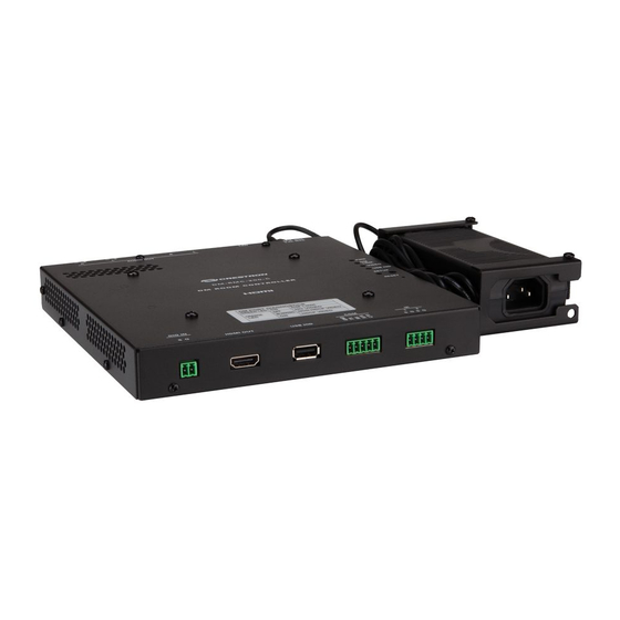
Install the Device
The Crestron
DM-RMC-200-C mounts into a 2-gang electrical box using the included support
®
bracket. The support bracket provides a holder for the included power pack.
Mounting the Device into an Electrical Box
To mount the device into an electrical box, do the following:
1. Using the four included 6-32 x 3/4" combo truss head screws, attach the support bracket
to the electrical box.
2. Ground the DM-RMC-200-C and connect the proper cables to the bottom of the unit.
Ground
RELAY:
To relay
controllable
devices
DIG IN:
Software programmable
digital output
AUDIO OUT:
Ampli ed stereo audio output
DM IN:
From DM
switcher, transmitter, or
®
other DM device or from HDBaseT
®
device
DO
Check the Box
QTY PRODUCT
1
Bracket, Support
2
Connector, 2-Pin
4
Connector, 2-Pin
2
Connector, 4-Pin
1
Connector, 5-Pin
1
Power Cord, 5' 10" (1.78 m)
1
Power Pack, 24 Vdc 2.5 A, 100-240 Vac
1
Screw, 6-32 x 1/2", Pan Head, Phillips
4
Screw, 6-32 x 1", Pan Head, Phillips
4
Screw, 6-32 x 3/4", Truss Head, Combo
2
Tie Wrap, Cable Tie, 15-1/2" x 1"
3. Using the four included 6-32 x 1" Phillips pan head screws, attach the DM-RMC-200-C to
the support bracket.
Inserting the Power Pack into the Power Pack Holder
To insert the power pack into the power pack holder, do the following:
1. Slide the power pack into the power pack holder.
2. Using the included 6-32 x 1/2" Phillips
pan head screw, thread the screw
through either of the two provided screw
holes to hold the power pack in place.
3. Bundle the excess cable of the power
pack into a loop, and then fasten the
bundled cable to the power pack holder
by doing the following:
a. Insert one of the included tie wraps
through one of the tie wrap holes in
the power pack holder.
b. Wrap the tie wrap around the
bundled cable.
c. Repeat steps 3a and 3b if
necessary using the other included
tie wrap and the remaining tie wrap
hole in the power pack holder.
COLOR
PART NUM.
2047590
2003574
2003582
2003576
2003577
2042043
2045873
Black
2007238
Black
2007250
2009211
Black
2013608
Screw
hole*
Tie wrap
hole
Tie wrap
Screw
hole
hole*
*Use either screw hole for the included
6-32 x 1/2" Phillips pan head screw.