レシーバー Crestron HD-RX3-FのPDF クイック・スタート・マニュアルをオンラインで閲覧またはダウンロードできます。Crestron HD-RX3-F 2 ページ。 Hd-tx, hd-rx series hdmi fiber-optic transmitters and receivers
HD-TX and HD-RX Series
HDMI
1
Introduction
The HD-TX and HD-RX Series consist of the following models:
•
HD-TX1-F transmitter and HD-RX1-F receiver
•
HD-TX3-F transmitter and HD-RX3-F receiver
2
Mounting
Mount the transmitter and receiver onto a wall or rack as
appropriate for your installation.
Wall Mounting
Using four mounting screws (not supplied), attach the
transmitter or receiver to the wall as shown below.
(4) Mounting screws
(not supplied)
Rack Mounting
Mount the transmitter or receiver to the front or rear rail of a
rack as follows:
1.
Position either the left or right mounting flanges of the
device so that the holes align with the holes in the rack
(mounting of right flanges is shown below).
2.
Secure the device to the rack using two rack mounting
screws (not supplied).
Rack mounting
screws
(not supplied)
1
For Regulatory Compliance information, refer to
the latest version of Doc. 6860.
QUICKSTART DOC. 6861D (2025032)
Fiber-Optic Transmitters and Receivers
®
3
HD-TX1-F and HD-RX-1 Connections
HD-TX1-F Front Panel Connections
Connecting the HDMI IN Port: Using an HDMI cable (not
supplied), connect the HDMI IN port to the HDMI output port of
the audio/video source.
Connecting the Control Ports: Connect the IR IN or COM
control port or both as follows:
•
IR IN: Using an IR cable (not supplied), connect the 2-pin
terminal block of the IR IN port to the IR output port of the
control system.
•
COM (RS-232): Using a data communications cable (not
supplied), connect the 3-pin terminal block to the COM port
of the control system.
HD-RX1-F Front Panel Connections
Connecting the HDMI OUT Port: Using an HDMI cable (not
supplied), connect the HDMI OUT port to the HDMI input port of
the receiving device.
Connecting the Control Ports: Connect the IR OUT or COM
control port or both as follows:
•
IR OUT: Using the Crestron
connect the 2-pin terminal block of the IR OUT port to the
IR input port of the device to be controlled.
•
COM (RS-232): Using a data communications cable (not
supplied), connect the 3-pin terminal block to the COM port
of the device to be controlled.
HD-TX1-F and HD-RX1-F Rear Panel Connections
Connecting the Ground: Connect the chassis ground lug to
earth ground (building steel).
Connecting the MM OPTICAL Fiber Port: Using a CresFiber
or other quality 50/125 μm or 62.5/125 μm simplex multimode
fiber-optic cable with SC connectors, connect one end of the
cable to the MM OPTICAL connector on the HD-TX1-F and the
other end of the cable to the MM OPTICAL connector on the
HD-RX1-F.
NOTE: For maximum distance, the fiber-optic
cable should be rated for at least 500 MHz*km
effective modal bandwidth (EMB) at both 850 nm
and 1300 nm. Refer to the cable manufacturer's
datasheet for EMB information.
Connecting the 12 Vdc Power Jack:
Connect the 12 Vdc power jack to the
PW-1205RU external power supply included
with the HD-TX1-F and HD-RX1-F.
www.crestron.com
08.16
Specifications subject to
change without notice.
HD-TX1-F Front Panel Connections
®
IRP2 emitter (not supplied),
HD-RX1-F Front Panel Connections
®
HD-TX1-F Rear Panel Connections
MM OPTICAL
Ground
CLASS 1
LASER
PRODUCT
USB port
(for factory
use only)
888.273.7876
201.767.3400
COM
IR IN
S G
HDMI IN
AV
source
Control
system
COM
IR OUT
S G
HDMI OUT
Display
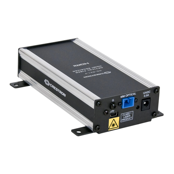
HD-RX1-F Rear Panel Connections
MM OPTICAL
12VDC
12VDC
0.5A
0.5A
Ground
CLASS 1
LASER
PRODUCT
USB port
Power
Power
(for factory
supply
supply
use only)
Fiber-optic cable