- ページ 21
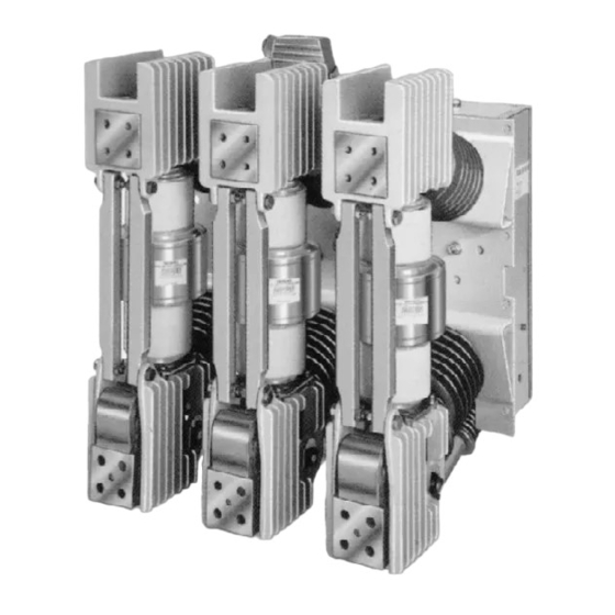
産業機器 Siemens 3AHのPDF 取扱説明書、インストール、操作、メンテナンスをオンラインで閲覧またはダウンロードできます。Siemens 3AH 33 ページ。 Vacuum circuit breaker operator module
Siemens 3AH にも: インストレーション オペレーション&メンテナンス (20 ページ), 取扱説明書 (38 ページ)

Maintenance
Electrical Close and Trip Check
(Control Power Required)
A check of the breaker control circuits is performed while
the unit is still connected to the switchgear by the plug
jumper. This check is made with the breaker energized by
control power from the switchgear.
1. Once the breaker springs are charged, move the Close/
Trip switch to the Close position. There should be both
the sound of the breaker closing and indication that
the breaker contacts are closed by the main contact
status indicator.
2. As soon as the breaker has closed, the automatic spring
charging process is repeated.
3. After a satisfactory close operation is verified, move
the Close/Trip switch to the Trip position. Verify by both
sound and contact position that the contacts are open.
Completion of these checks demonstrates satisfactory
operation of auxiliary switches, internal relays and so-
lenoids.
Checks of the Spring Charging Motor
No additional checks of the spring charging motor are nec-
essary.
Vacuum Interrupters
The life expectancy of vacuum interrupters is a function of
the number of interruptions and magnitude of current in-
terrupted (Table 3 and Figure 15).
They must also be replaced before certain amount of me-
chanical operations (Table 5) or when the contacts have
been eroded beyond allowed limits. Vacuum tube replace-
ment procedures are detailed in the following maintenance
instructions.
The curve is Figure 15 is offered as a guide to life expectancy.
Interrupter Vacuum Check Mechanical (Figures 16)
Before putting the breaker into service, or if an interrupter
is suspected of leaking as a result of mechanical damage,
check the vacuum either mechanically as described in this
section or alternatively electrically using a high potential
test set as described in the next section.
Open and isolate the breaker and detach the insulated cou-
pler (48) from lever (48.6) (Figure 16).
The atmospheric pressure will force the moving contact of
a hermetically sealed interrupter into the "Closed" posi-
tion, causing lever (48.6) to move into the position shown
in Figure 16.
A vacuum interrupter may be assumed to be intact if it
shows the following characteristics:
An appreciable closing force has to be overcome when
lever (48.6) is moved to the "Open" position by hand Fig-
ure 16. When the lever is released, it must automatically
return to the "Closed" position with an audible sound as
the contacts touch.
After checking the vacuum, reconnect the lever (48.6) to
the insulated coupler (48).
High-Potential Tests
The next series of tests (Vacuum Integrity Test and Insula-
tion Tests) involve use of high voltage test equipment. The
breaker under test should be inside a suitable test barrier
equipped with warning lights.
Vacuum Integrity Check (using Dielectric Test)
A high potential test is used to verify the vacuum integrity
of the circuit breaker. The test is conducted on the circuit
breaker with its primary contacts in the Open position.
Hazardous voltages used in high potential
tests.
Will cause severe personal injury and
death.
Follow safe procedures, exclude unnecessary
personnel and use safety barriers. Keep
away from the breaker during application of
test voltages.
Disconnect the plug jumper from between
the circuit breaker and switchgear before
conducting high potential tests.
After test completion, ground both ends and
the middle portion of the vacuum interrupter
to dissipate any static charges.
Vacuum interrupters may emit X-ray
radiation.
Can cause personal injury.
Keep personnel more than six (6) feet away
from a circuit breaker under test.
High Potential Test Voltages
The voltages for high potential tests are shown in Table 4.
Table 4. High Potential Test Voltages
Equipment kV
Max AC rms
Rating
4.76kV
8.25kV
15kV
27kV
38kV
Max DC Avg
14kV
20kV
27kV
38kV
27kV
38kV
45kV
64kV
60kV
85kV
20
