- ページ 17
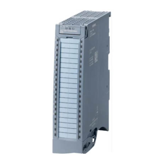
産業機器 Siemens Simatic S7-1500/ET 200MPのPDF マニュアルをオンラインで閲覧またはダウンロードできます。Siemens Simatic S7-1500/ET 200MP 41 ページ。 Digital input module di 16x24vdc ba
Siemens Simatic S7-1500/ET 200MP にも: 設備マニュアル (34 ページ), マニュアル (28 ページ), マニュアル (35 ページ)

Parameters/address space
4.4 Address space
Low limit 1 or 2
Specifies the low limit threshold that triggers hardware interrupt 1 or 2.
High limit 1 or 2
Specifies the high limit threshold that triggers hardware interrupt 1 or 2.
4.4
Address space
The module can be configured differently in STEP 7; see following table. Depending on the
configuration, additional/different addresses are assigned in the process image of the inputs.
Configuration options of AI 16xU BA
You can configure the module with STEP 7 (TIA Portal) or with a GSD file.
When you configure the module by means of the GSD file, the configurations are available
under different abbreviations/module names.
The following configurations are possible:
Table 4- 3
Configuration options
Configuration
1 x 16-channel without value status
1 x 16-channel with value status
1 x 16-channel with value status for
module-internal shared input with
up to 4 submodules
Value status (Quality Information, QI)
The value status is always activated for the following module names:
• AI 16xU BA QI
• AI 16xU BA MSI
An additional bit is assigned to each channel for the value status. The value status bit
indicates if the read in digital value is valid. (0 = value is incorrect).
16
Short designation/
module name in the
GSD file
AI 16xU BA
AI 16xU BA QI
AI 16xU BA MSI
Configuration software, e.g., with STEP 7 (TIA Portal)
Integrated in the hardware
catalog STEP 7 (TIA Portal) as
of V16 and HSP 0312
X
X
X
(PROFINET IO only)
Analog input module AI 16xU BA (6ES7531-7LH00-0AB0)
Equipment Manual, 09/2020, A5E47052556-AA
GSD file in
STEP 7 (TIA Portal) V12
or higher or STEP 7 V5.5
SP3 or higher
X
X
X
(PROFINET IO only)
