- ページ 3

産業機器 Siemens Simatic S7-300のPDF はじめにをオンラインで閲覧またはダウンロードできます。Siemens Simatic S7-300 8 ページ。 Automation systems, controlling a physical axis
Siemens Simatic S7-300 にも: ユーザーマニュアル (34 ページ), マニュアル (21 ページ), 操作説明 (4 ページ), 操作説明 (5 ページ), マニュアル (35 ページ), はじめに (16 ページ), アプリケーション概要 (24 ページ), マニュアル (18 ページ), マニュアル (32 ページ), インストールおよびハードウェアマニュアル (20 ページ), はじめに (32 ページ)
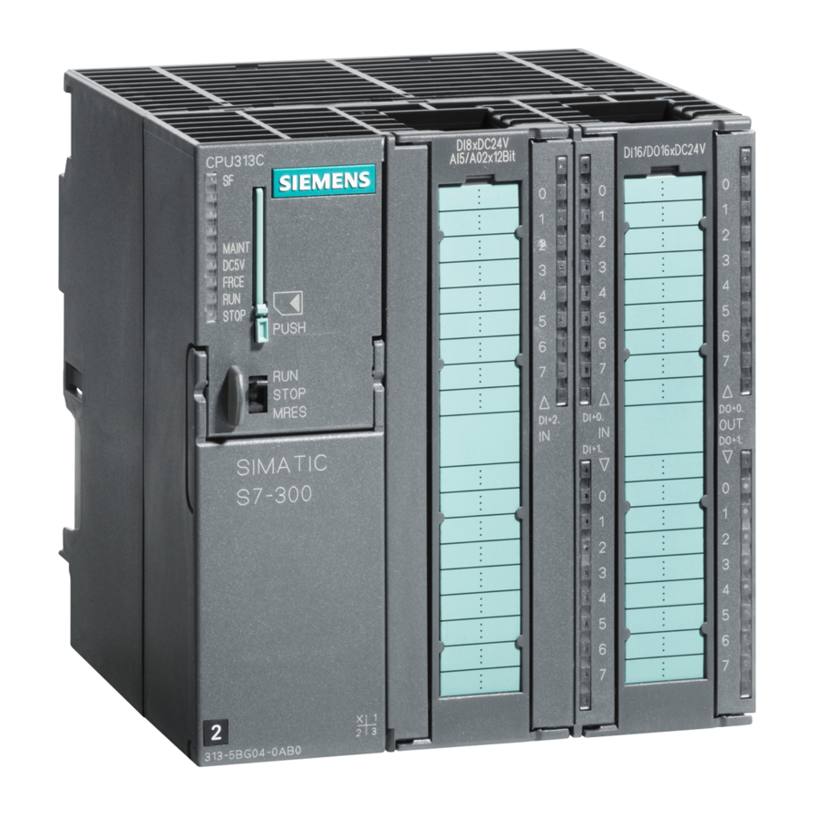
Siemens Simatic S7-300 はじめに
Layout of the example
Power supply
ON/OFF
Clamp for
strain relief
Overview of the layout of the example (without the wiring of the power supply to the SM)
Functionality of the Example
Output A4.0 can only be switched (i.e. the A4.0 diode lights up on the DO), if switches E0.1
and E0.2 are pressed.

Step 1: Installation

Installation sequence: from left to right: PS – CPU – DI – DO.
A bus connector (BV) is shipped with each DI and DO. You can get an idea of the overall con-
figuration in the overview figure.
Figure
S7-300 Programmable Controller, Getting Started, First Steps for Installation and Commissioning
A5E00069340 01 // 04/2000
Switch for setting
Mode selector switch
system voltage
E0.1
E0.2
Power connector
1. Put the rail in position and fasten (screw size: M6) so that
there is at least 40 mm above and below the rail.
If you fasten the rail to a grounded metal plate or a grounded
device support, make sure there is a low-resistance connec-
tion between the rail and the base.
2. Connect the rail to the protective conductor. There is an M6
protective conductor screw on the rail for this purpose.
Minimum cross-section of the cable to the protective conduc-
tor: 10 mm
Rail
A4.0
Programming device
Switches
cable
Installing and Grounding the Rail
2
.
Programming
device with
STEP 7 software
3