- ページ 4

産業機器 Siemens Simatic S7-300のPDF マニュアルをオンラインで閲覧またはダウンロードできます。Siemens Simatic S7-300 32 ページ。 Automation systems, controlling a physical axis
Siemens Simatic S7-300 にも: ユーザーマニュアル (34 ページ), マニュアル (21 ページ), 操作説明 (4 ページ), 操作説明 (5 ページ), マニュアル (35 ページ), はじめに (8 ページ), はじめに (16 ページ), アプリケーション概要 (24 ページ), マニュアル (18 ページ), インストールおよびハードウェアマニュアル (20 ページ), はじめに (32 ページ)
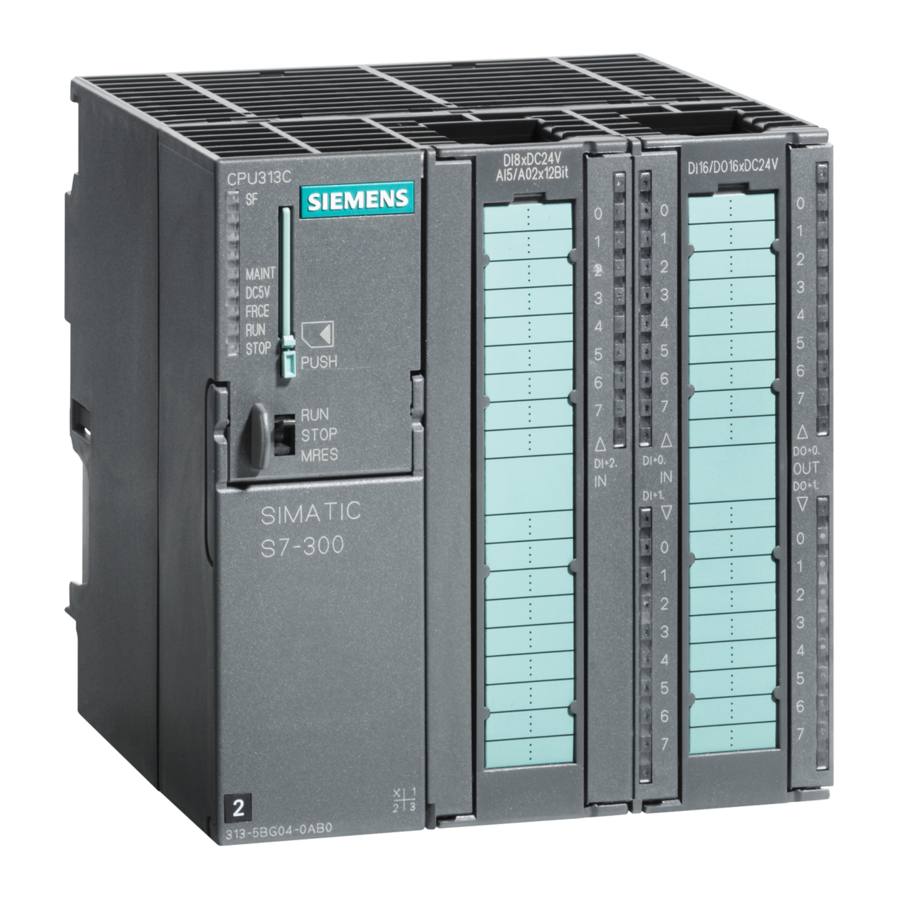
Siemens Simatic S7-300 マニュアル
Terminal assignment diagram for the redundant supply of sensors
The figure below shows how sensors can additionally be supplied by means of Vs
with a redundant voltage source – for example, via another module.
Figure 2
Terminal assignment diagram of the resistor wiring of the sensors
To detect a wire break, it is necessary to wire sensor contacts with a resistor.
Figure 3
4
Short-circuit-
proof driver
Digital input
module
Terminal assignment diagram for the redundant supply of sensors of the SM
321; DI 16
DC 24 V
L +/ V
s
15 kW ... 18 kW
Terminal assignment diagram of the resistor wiring of the sensors of the SM
321; DI 16
DC 24 V
Product Information on the Manual S7-300 Module Specifications, Edition 11/2002
L+
1 L+
Vs
2 L+
M
±
to the sensors
E x.x
A5E00213444-02