- ページ 9

産業機器 Siemens Simatic S7-300のPDF マニュアルをオンラインで閲覧またはダウンロードできます。Siemens Simatic S7-300 32 ページ。 Automation systems, controlling a physical axis
Siemens Simatic S7-300 にも: ユーザーマニュアル (34 ページ), マニュアル (21 ページ), 操作説明 (4 ページ), 操作説明 (5 ページ), マニュアル (35 ページ), はじめに (8 ページ), はじめに (16 ページ), アプリケーション概要 (24 ページ), マニュアル (18 ページ), インストールおよびハードウェアマニュアル (20 ページ), はじめに (32 ページ)
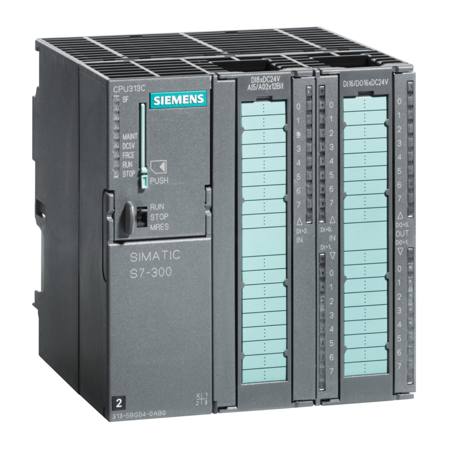
Siemens Simatic S7-300 マニュアル
1.3
Behavior and diagnostics of the SM 321; DI 16
Effect of operating and mode supply voltage on the input values
The input values of the SM 321; DI 16
the CPU and the supply voltage of the module.
Table 4
CPU Operating State
POWER ON
POWER OFF –
Diagnostic messages of the SM 321; DI 16
The table below provides an overview of the diagnostic messages of the SM 321;
DI 16
Table 5
Diagnostics Message
Sensor supply missing
Wire-break
Module not parameterized
External auxiliary supply missing
Internal auxiliary power missing
Fuse blown
Incorrect parameter on module
Watchdog timeout
EPROM error
RAM error
Hardware interrupt lost
Product Information on the Manual S7-300 Module Specifications, Edition 11/2002
A5E00213444-02
Dependencies of the input values of the operating mode of the CPU and the
supply voltage L+ of the SM 321; DI 16
RUN
L+ exists
L+ missing
STOP
L+ exists
L+ missing
L+ exists
L+ missing
DC 24 V.
Diagnostic messages of the SM 321; DI 16
DC 24 depend on the operating mode of
DC 24 V
Power Supply L+
to Digital Module
DC 24 V
DC 24 V
LED
Scope of the
Diagnostics
SF
Channel group
SF
Channel group
SF
Channel group
SF
Module
SF
Module
SF
Module
SF
Module
SF
Module
SF
Module
SF
Module
SF
Module
DC 24 V
Input Value of Digital
Module
Process value
0 signal
Process value
0 signal
Parameters
can be
assigned
Yes
No
9