- ページ 15
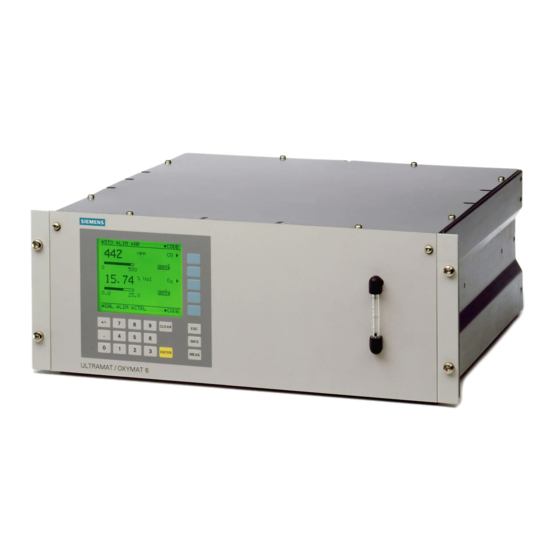
産業機器 Siemens ULTRAMAT 6FのPDF 追加装備マニュアルをオンラインで閲覧またはダウンロードできます。Siemens ULTRAMAT 6F 20 ページ。 Gas analyzer for the determination of ir-absorbing gases
Siemens ULTRAMAT 6F にも: 取扱説明書 (49 ページ), 安全マニュアル (24 ページ)

English
4.
Commissioning
Commissioning can only be performed properly when the person doing the commissioning is familiar
with the contents of the manuals and operating instructions provided. The warnings in the individual
manuals must be observed in particular.
4.1
Connection to the EEx p safety device
The analyzer must be connected to the EEx p safety device as shown in the assembly diagrams 3.2
and 3.3:
Check the power supply
-
Seal all unnecessary cable glands using the supplied plugs
-
Screw in the occupied screw cable glands carefully
-
Close the doors. The screws must be tightened evenly until the door frame touches the housing
-
surface
Connect protective gases with required pressure (0.2...0.4 MPa upstream of pressure regulator)
-
Set the pressure regulator of the EEx p safety device to at least 0.2 MPa.
-
When measuring combustible gases with the type of protection EEx p with "Compensation of losses
resulting from leaks" it must be ensured that the sample gas pressure applied to the analyzer is not
more than 160 hPa (160 mbar) above the ambient pressure and always more than 5 hPa below the
purging gas pressure. If this condition cannot be met with fail safety, a differential pressure monitor
must be inserted between the sample gas and purging gas as additional protection.
The analyzer may then be started by opening the protective gas line and switching on the power
supply – under consideration of the measures described above.
4.2
Pressure correction
There is an internal pressure sensor in the U 6F for correcting the influence of air pressure. This is
connected to the ambient air by a pipe. To avoid explosive atmosphere diffusing into the pressure
sensor, this pipe must be connected with a hose which ends in the Ex-free zone.
A higher sample gas pressure up to 1500 hPa can only be measured with an external pressure
sensor. Its signal must be fed intrinsically-safe into the analyzer. Its parts which come into contact with
the sample gas must meet the requirements of the measurement. The connection and
parameterization are described in the appropriate equipment manual.
In the O 6F the influence of the sample gas pressure up to 2000 hPa can be corrected with the
internal pressure sensor. A higher pressure up to 3000 hPa can only be measured with an external
absolute pressure sensor.
4.3
Key switch
The Ex protection of the EEx p safety device can be deactivated (key inserted in the lock) using a key
switch (bypass switch). In this manner, the analyzer can also be connected electrically without
protective gas purging (e.g. for maintenance work).
Some EEx p safety devices offer the possibility of effecting the key switch function with an operating
function (key code).
Commissioning with the "key switch" always requires permission of the user or a person authorized by
him. It may only be granted if it is certain that there is no explosive atmosphere for the duration of the
planned work or if the necessary precautions against the risk of explosion have been taken (so-called
"Firing permission").
At the end of maintenance work, make absolutely sure that the key switch is turned off again.
E-12
Additional Equipment Manual EEx p
Order No.:
A5E 000
58873-02
