- ページ 4
産業機器 Siemens UP 588/13のPDF 技術仕様をオンラインで閲覧またはダウンロードできます。Siemens UP 588/13 6 ページ。 Colour touch panel

GAMMA instabus
Technical Specification
March 2010
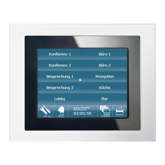
Colour touch panel UP 588/13
Colour touch panel UP 588/23
Accessories:
Design frame aluminium
Design frame stainless steel design
Design frame glass black
Design frame glass white
flush-type box
The bus cable is connected via a standard bus terminal D,
which is plugged into the corresponding terminal slot on
the right side of the housing. On the left, beside the
plug-in slot for the bus terminal are the programming
button C and the programming LED B. The connection
terminal for the 230 V power supply or, in the 24 V
version for 24 V supply are on the left side A of the
device. The terminal must be removed to connect the
power supply.
It is essential to obey the connection sequence marked
on the housing!
Mounting and wiring
General description
The device 2 may only be mounted in the flush-type box
1, to be ordered as an accessory. When the cable is
brought into the flush-type box, take care that the bus
cable is fed in through the bottom left hand recess and
the power supply cable is fed in through the right hand
recess. The bus and power supply cables must not be fed
into the flush-type box through the same recess. Inside
the box, the cable is to be routed so that there is a
guaranteed separation of at least 10 mm between bus
and power supply cables.
Connecting the bus cable (figure 4 "A")
− The bus terminal (C3) is suitable for solid conductors
with a diameter of 0.6 ... 0.8 mm.
− Strip off approx. 3 cm of the bus cable insulation
− Strip the insulation from the conductors (C3.4) to a
distance of approx. 5 mm and plug it into the
terminal (C3) (red = +, grey = -).
Clipping on bus terminal (figure 4)
− Plug the bus terminal into the guide slot and press it
(C3) downwards to the end stop
Technical Manual
Update: http://www.siemens.com/gamma
2.3.1.7/4
C3.3 C3.2
C3
C3
Connecting the power supply (Figure 4 "B")
− Strip the insulation from the conductor (C4.1) to a
distance of 6...7 mm, plug it into the power supply
connection terminals (C4) and tighten the screws
(C4.2).
Terminal assignment:
230V
1
2 N Neutral conductor
3 L Phase
After connecting the bus terminal and the power supply
to the conductors, the terminals are plugged into the
corresponding outlets on the touch panel. The power
supply must only be switched on when the plug is
engaged firmly in the device. After switching on the bus
voltage and the power supply, the programming button
can be pressed and the physical device address
programmed. The LED must go out after programming
the physical address.
The device is then screwed into the flush-type box with
the four screws 3 enclosed (see figure 3).
The protective film applied to the display surface can
now be removed. Do not use any sharp items or tools to
do this.
After the screwing the display modul and the removal of
the protective film, the design frame 4 can be plugged
UP 588, 6 pages
© Siemens AG 2010
Subject to change without further notice
5WG1 588-2AB13
5WG1 588-2AB23
5WG1 588-8AB12
5WG1 588-8AB13
5WG1 588-8AB14
5WG1 588-8AB15
5WG1 588-8EB01
C3
C3.1
C3.4
C4.2
5 mm
C4
C3.4
6....7mm
"A"
Figure 4: Connections
24V
Earth
In1:
not connected
In2:
Industry Sector, Building Technologies
Low Voltage Distribution
PO Box 10 09 53, D-93009 Regensburg
C4.1
"B"
± DC: AC
± DC: AC
Siemens AG
