- ページ 32
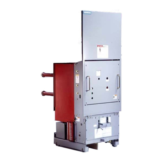
スイッチ Siemens 15-FSV-750のPDF インストレーション オペレーション&メンテナンスをオンラインで閲覧またはダウンロードできます。Siemens 15-FSV-750 48 ページ。 Vacuum circuit breakers fsv series and msv series

Interrupter/Operator
Maintenance
1 - "
40
Cross Arm
1 4
Post I ns u lator
16
Lower pole support
40
Figure 21a Lower Pole Support With Insulated Coupler
open. Test voltage should be raised g radually, and the contact
gap must sustain the voltages l i sted below, appropriate tor
the b reakers rat i n g , for one m i n ute. I t it does not, the interrupter
is faulty and m u st be replace d .
B reaker Max. KV
A.C. Potential
kV
5
14
kV
1 5
27
A
H I G H PEAK VOLTAGES CAN RESULT I N
E R R O N E O U S TEST R E S U LTS
TION CAU S I N G PE RSONAL I NJ U RY
DC h i g h potential test voltage sources u s i n g
halt-wave conve rsion will a p p l y peak volt
ages
times g reater than the measured av
3
erge DC voltage. Repetitive application of
h i g h peak voltage can result i n erroneous
test results
inju ry.
Do not use DC high potential voltage sources
which em ploy half-wave conversion c i rc u its.
48 .5 48
1 6
1 4
Pin
48 . 5
Lever
48 .6
I n s u lated Coupler
48
D.C. Potential
kV
20
kV
38
CAUTION
X-RA D I A
&
X-Rad i ation causing personal
&
A
H i g h Potential Tests e m ploy extremely haz
ardous voltages which will cause severe
personal i nj u ry and death.
Follow sate proced u r e , exc l u d e u n neces
sary personnel, barrier test vehicle and keep
we l l away from b reaker d u ri n g test voltage
application. After test, g round ends and
middle of vacuum tube to remove static
charge.
A
Vac u u m I nterrupters can emit X-Rad iation
c a u s i ng personal inju ry.
Do not apply test voltages to the i nterrupters
which exceed the values l i sted below. All
personnel m u st remain a m i n i m u m of six teet
away from i nterrupter u n d e r test.
Vacuum Tube Replacement
Replacement interru pters are f u rn i sh ed as a complete assem
bly. They have been completely tested and d i electrically and
mechanically conditioned . The i nterrupters, when i n stal led , d o
n o t req u i re t h a t t h e y be operated no-load a s e t numbe r of times
or voltage tested to condition the contacts
It i s recommended t h at one interru pter be removed and re
placed completely rather than removing two o r more interru pt
ers at a time. The fol l owing proced u re in check list format
desc ribes the p roced u re tor removing and replacing a vac
uum i nterrupter. Components may be i dentified by reference
to fig u re
6, 7, 8, 22 & 23.
Removing The I nterrupter
1.
Before starting work, the c i rcuit b reaker should be
1 .1
isolated from all p rimary and control power sou rces
and all stored energ y d i scharged by trippi n g , clos
ing , and tripping the breake r b y hand . D i scharg e any
static charge by g rounding al l and center metal sec
tions of t h e vacuum interru pter. Caref u l l y remove ex
terior and interphase barriers.
Page
DANGER
CAUTION
2 7
