- ページ 36
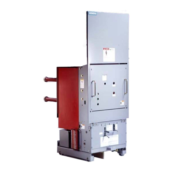
スイッチ Siemens 15-FSV-750のPDF インストレーション オペレーション&メンテナンスをオンラインで閲覧またはダウンロードできます。Siemens 15-FSV-750 48 ページ。 Vacuum circuit breakers fsv series and msv series

Interrupter/Operator
Maintenance
of (30 Ft. Lbs ) 40 N m , taking care to see that the
terminal of the i nterrupter i s not s u bjected to exces
sive bending movement .
NOTE:
Excess1ve ben d 1 ng movement exerted wh1le fasten 1 ng the
terminal clamp w1ll damage the vac u u m Interrupter
2 8
Al1gn pole su pport, 20. correctly and t1ghten bolt fas
tening 1t to the post insulator Fasten secu rely a l l bolts
assoc1ated with struts . 28
2 . 9
T1ghten Interrupter fastenmg bolt ' B o n t h e upper
pole s u pport, 20, hold1ng the i nterrupter f1rmly by 1ts
upper 1nsu lator. and operate levers, 48 6. by hand to
see whether the movable contact moves freely If any
b1nd1ng or lack of freedom is noted . loosen bolt ' B '
a n d adjust t h e Interrupter 1n pole s u pport b y turning
and movmg 1t s l 1ghtly
2 . 1 0 Press centenng ring segments f1rmly aga1nst base of
tube. and fasten sec urely On some breaker a one
p1ece r1ng is used, and th1s IS s1mply fastened 1n
place
2 . 1 1 Attach 1nsulat1ng coupler, 48. and lever. 48.6 together
us1ng pin 4 8 . 5 . Apply reta1n1ng clips Correct pin has
have
ends wh1ch
been generously c h a m fered
2 1 2 Open and close breaker several times, and then check
to see that a l l bolted JOints and devices are tight
3
Check1ng the Contact Stroke
Open the c 1 rc u i t breaker
3. 1
3 2
Free 1nsulat1ng coupler, 48, by remov1ng pin 4 8 . 5 .
T h e interrupter contacts must now c lose automat i
c a l l y as a consequence o f atmospheriC press u re
3 . 3
Observe the term1nal clamp, 29.2 thru t h e openings
on each s1de of the lower pole support, 40. Us1ng
vern1er c a l 1 pers measu re the d1stance from the bot
tom su rface of the term1nal clamp to the bottom edge
of the c utout open i n g . Measure carefully. and record
your result.
3 . 4
Connect t h e insulat1ng cou pler. 4 8 . u s i n g p i n . 4 8 . 5 ,
and t h e retain1ng c l i ps provided
3 5
Repeat the measurement desc r 1 bed 1n step 3 3 aga1n
with care to max1 m ize accu racy, record you r result
3.6
Determine difference between the measurements
made under steps 3.3 and 3 . 5 . You r result should
be
Type 5-MSV-250 Breakers 5 to 7mm (0 20 to 0 . 2 7
i nches)
Type 7-FSV-500, 1 5- FSV-500. and 1 5-FSV- 750 B reak
ers 1 0 to 1 2m m ( 0 . 40 to 0 . 4 7 Inches)
Type 5-FSV-350, 1 5-FSV- 1 000 and all 3000A break
ers 7.5 - 8 . 5m m (0.30 - 0.33 mches)
3. 7
If you fail to achieve the l i sted results carefu l ly repeat
t h e e n t i r e p ro c e d u r e m a k 1 n g c e r t a i n of y o u r
measu rements.
3 . 8
I f , after confirming your measurements , a n d you find
the stroke not i n ag reement with the values g iven
above, an adjustment can be made by adjusting the
eyebolt , 4 8 . 6 . 5 .
Excessive stroke is corrected b y turning t h e eyebolt
•
out.
Insufficient stroke i s corrected by turning the eye
•
bolt i n .
3 . 9
Loosen locking n u t on eyebo l t , on insulated coupler
(48) and retain position of the eye Make adjustments
i n one-half turn i ncrements. After adjustment is com
tighten eyebolt locking nut to 30
pleted ,
(40
::+::
5 N m ) .
4 .
After eyebolt i s tightened to proper torq u e , repeat a l l
measurement proced u res making certain they a r e i n
agreement w i t h values indicated in 3.6
5 .
Complete all other maintenance p rocedu res. Com
pletely reassembled breaker should pass high po
tential test before i t is ready for service.
Hydraulic Shock Absorber
The 3AF mechanism is equ i pped with hydraulic shock ab
sorber and a stop bar that functions when the breaker opens.
See item 61 .8 F i g u re 11. The shock absorber should req u i re no
adjustment. However, at maintenance checks , the shock ab
sorber should be examined for evidence of leaking. I f evi
dence of fluid leakage i s foun d , the shock absorber must be
replaced to prevent damage to the vacu u m interrupter bellows.
Page 31
::+::
4 lb. ft.
