- ページ 5
ランタン Digital Lumens RLEのPDF 取付説明書をオンラインで閲覧またはダウンロードできます。Digital Lumens RLE 20 ページ。 Intelligent led high-bay luminaire
Digital Lumens RLE にも: 取付説明書 (20 ページ)
RLE
GETTING STARTED
Verify Optic Type
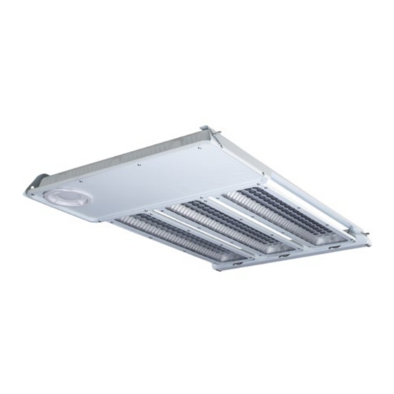
Review the RLE dimensional drawings, above
(Illustration 1).
Use optic type specified in the project plan — Wide or
Narrow.
The optic type is printed on the luminaire label
Note:
(Illustration 2).
Add Tracking Labels to Sticker Book
Detach plastic bag from luminaire, then remove product and
controller barcode label assembly from bag and affix to sticker
book, as depicting the intended installation location of the
luminaire (Illustration 3).
Make Electrical Connections
Suitable for cords 0.06 – 0.1 inch
Do not connect or disconnect while under load.
Remove (2x) Phillips
®
compartment access panel (Illustration 4a).
Extract the internal three-wire bundle from wiring
compartment (Illustration 4b) and identify the wire leads
(Illustration 4c).
Connect external wiring to internal wire bundle using
splicing connectors (Illustration 4d).
supplied WAGO
®
Option A: Use supplied cable gland or suitable IP-rated
wiring connector (supplied by installer) to route power
cable through access panel (Illustration 4e).
or
Option B: Used supplied pre-assembled IP-rated wiring
connector (supplied by installer) to route power cable
through access panel (Illustration 4f).
Replace wiring compartment access panel and tighten
screws to 7.1 kgf-cm (Illustration 4g).
Install Luminaires
Note:
Luminaire must be positioned at least 8 inch (203 mm)
from ceiling.
Fastening hardware supplied by installer.
Option 1: Aircraft Cable – RLE-D1/H1
—
Refer to sticker book to confirm the correct location
and placement of luminaire.
—
Secure aircraft cable to a beam or truss.
RLE Installation Instructions
(1.5 – 2.5 mm
)
2
2
screws retaining the wiring
—
Connect cable to luminaire housing using aircraft
cable hanging hardware (Illustration 5a).
—
Use a box level to level the luminaire.
For aisle illumination, verify that luminaire is oriented
Note:
correctly (Illustration 5b).
Option 2: Aircraft Cable – RLE-P1
—
Refer to the sticker book to confirm the correct
location and placement of the luminaire.
—
Secure aircraft cable to a beam or truss.
—
Connect cable to luminaire housing using aircraft
cable hanging hardware (Illustration 5c).
—
Use a box level to level the luminaire.
Note:
For aisle illumination, verify that luminaire is oriented
correctly (Illustration 5d).
Option 3: Rigid Mount – RLE-D1/H1/P1
—
Refer to sticker book to confirm the correct location
and placement of luminaire.
—
Assemble mounting bracket and make sure the legs
go under the lip (Illustration 5e).
—
Fasten mounting bracket screws (Illustration 5f).
—
Snap luminaire into mounting bracket and fasten
screws into luminaire housing, ensuring that they are
fully inserted (Illustration 5g).
—
Secure mounting bracket and luminaire to mounting
surface.
—
Use a box to level the luminaire.
Note:
For aisle illumination applications, verify that
luminaire is oriented correctly in relation to the aisle axis
(Illustration 5b and 5d).
Verify Sticker Book
To prevent issues during commissioning, ensure that
the placement of the bar code label in the sticker book
corresponds to the luminaire's physical location in the facility.
Rotate Light Bars
Rotate the lightbars into position as specified in the
project plan (Illustration 6).
Ensure at the light bar release buttons are secured
Notes:
within the appropriate detents.
Refer to Appendix A for typical lightbar positioning
examples.
ENGLISH
5