- ページ 4
ネットワーク・ルーター Cisco 2821 SeriesのPDF オペレーションをオンラインで閲覧またはダウンロードできます。Cisco 2821 Series 31 ページ。 2800 series integrated services routers
Cisco 2821 Series にも: インストールとアップグレード (21 ページ), データシート (20 ページ), オペレーション (31 ページ), クイック・スタート・マニュアル (47 ページ)

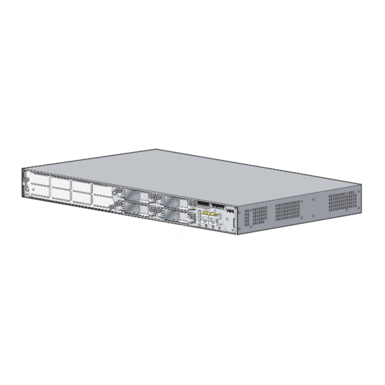
Cisco 2811 and Cisco 2821 Routers
shows the rear panel. The front panel contains 4 LEDs that output status data about the system power,
auxiliary power, system activity, and compact flash busy status. The back panel consists of 12 LEDs:
two Ethernet activity LEDs, two duplex LEDs, two speed LEDs, two link LEDs, two PVDM LEDs, and
two AIM LEDs.
The front panel contains the following:
(1) Power inlet
•
(2) Power switch
•
(3) Optional RPS input
•
(4) Console and auxiliary ports
•
(5) USB ports
•
(6) CF drive
•
(7) LEDs described in table 1.
•
The back panel contains the following:
(1) Ground connector
•
(2) and (3) Ethernet ports and LEDs
•
(4)-(7) HWIC slots
•
(8) ENM slot.
•
Table 1
of the router:
Table 1
Name
System Power
Auxiliary Power Off
Activity
Compact Flash
1. However, an AIM module may not be installed in accordance with this security policy. There is a separate
security policy covering the Cisco 2811 and Cisco 2821 routers with AIM module installed.
Cisco 2811 and Cisco 2821 Integrated Services Router FIPS 140-2 Non Proprietary Security Policy
4
and
Table 2
provide more detailed information conveyed by the LEDs on the front and rear panel
Cisco 2811 Front Panel Indicators
State
Off
Blinking Green
Solid Green
Solid Orange
Solid Green
Solid Orange
Off
Blinking Green
Solid Green
Off
Solid Green
Description
Power off
ROMMON mode
Operating normally
System Error Detected
-48V PS and RPS not present
-48V PS or RPS present and functional
-48V PS or RPS present and failure detected
No interrupts or packet transfer occurring
System is servicing interrupts
System is actively transferring packets
No ongoing accesses, eject permitted
Device is busy, do not eject
OL-8663-01
