- ページ 12
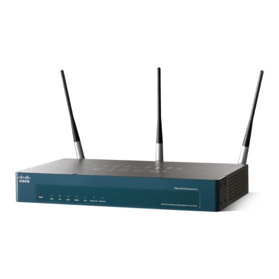
無線アクセスポイント Cisco Small Business AP541NのPDF クイック・スタート・マニュアルをオンラインで閲覧またはダウンロードできます。Cisco Small Business AP541N 17 ページ。 Small business pro series dual-band single-radio access point
Cisco Small Business AP541N にも: パンフレット (2 ページ), クイック・スタート・マニュアル (20 ページ)

Prepare the Device
To prepare the device, do the following:
Attach the antennas to the RP-SMA connectors labeled ANT101,
S
1
TEP
ANT102, and ANT103. The antennas are all the same, so which
antenna is attached to what connector is of no consequence.
Determine where you want to locate the access point. If you are
S
2
TEP
using AC power, make sure the location is within reach of an AC
power outlet.
Keep enough ventilation space for the access point and check for
S
3
TEP
any other environmental restrictions.
Wall Mounting
Before you begin, you need 2 wallboard screws (included) to mount the
access point. We recommend using screws with a minimum of 4mm width
at the head and a shaft diameter of at least 1.5mm.
Insecure mounting might damage the device or cause injury.
W
ARNING
Cisco is not responsible for damages incurred by insecure wall-
mounting.
To mount the access point to the wall:
Determine where you want to mount the access point. Verify that
S
1
TEP
the surface is smooth, flat, dry, and sturdy.
Drill two pilot holes into the surface 5.75 inches (146 mm) apart,
S
2
TEP
and with a minimum of 4.0 inches (101 mm) of clearance.
Insert a screw into each hole, leaving a gap between the surface
S
3
TEP
and the base of the screw head of at least 0. 1 inches (3 mm).
Place the access point wall-mount slots over the screws and slide
S
4
TEP
the access point down until the screws fit snugly into the wall-
mount slots.
Cisco AP541N Dual-band Single-radio Access Point Quick Start Guide
11
