- ページ 3
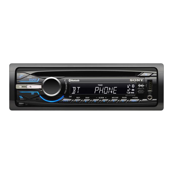
ステレオシステム Sony MEX-BT3900UのPDF サービスマニュアルをオンラインで閲覧またはダウンロードできます。Sony MEX-BT3900U 48 ページ。 Bluetooth audio system
Sony MEX-BT3900U にも: インストール/接続 (2 ページ), インストール/接続 (2 ページ), 仕様 (4 ページ), インストール/接続 (2 ページ), オーナーの記録 (45 ページ)

TABLE OF CONTENTS
1.
2.
..................................................................
3.
3-1. Disassembly Flow ........................................................... 13
3-2. Cover ............................................................................... 13
3-3. CD Mechanism Deck (MG-101P-188//Q) ...................... 14
3-4. ANTENNA Board ........................................................... 14
3-5. MAIN Board (with BT Board) ....................................... 15
3-6. SERVO Board ................................................................. 15
3-7. Chassis (T) Sub Assy ...................................................... 16
3-8. Roller Arm Assy .............................................................. 16
3-9. Chassis (OP) Assy ........................................................... 17
3-10. Chucking Arm Sub Assy ................................................. 17
3-11. Sled Motor Assy .............................................................. 18
3-12. Optical Pick-up Section .................................................. 19
3-13. Optical Pick-up ............................................................... 19
4.
............................................................ 19
5.
5-1. Block Diagram - AUDIO Section (1/2) - ........................ 20
5-2. Block Diagram - AUDIO Section (2/2) - ........................ 21
- PANEL, POWER SUPPLY Section - ........................... 22
5-4. Printed Wiring Boards - MAIN Section - ....................... 24
5-5. Schematic Diagram - MAIN Section (1/3) - ................... 25
5-6. Schematic Diagram - MAIN Section (2/3) - ................... 26
5-7. Schematic Diagram - MAIN Section (3/3) - ................... 27
5-8. Printed Wiring Board - KEY Board -.............................. 28
5-9. Schematic Diagram - KEY Board - ................................ 29
6.
6-1. Main Section ................................................................... 35
6-2. Front Panel Section ......................................................... 36
6-3. CD Mechanism Section (MG-101P-188//Q) .................. 37
7.
Accessories are given in the last of the electrical parts list.
.............................................
.............................. 38
MEX-BT39UW/BT3900U/BT3950U
SERVICING NOTES
NOTES ON HANDLING THE OPTICAL PICK-UP
BLOCK OR BASE UNIT
3
The laser diode in the optical pick-up block may suffer electro-
static break-down because of the potential difference generated by
7
the charged electrostatic load, etc. on clothing and the human body.
During repair, pay attention to electrostatic break-down and also
use the procedure in the printed matter which is included in the
repair parts.
The fl exible board is easily damaged and should be handled with
care.
NOTES ON LASER DIODE EMISSION CHECK
Never look into the laser diode emission from right above when
checking it for adjustment. It is feared that you will lose your sight.
If the optical pick-up block is defective, please replace the whole
optical pick-up block.
Never turn the semi-fi xed resistor located at the side of optical
pick-up block.
semi-fixed resistor
SECTION 1
optical pick-up
3
