- ページ 3
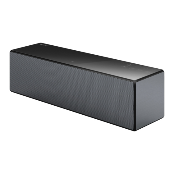
ステレオシステム Sony SRS-X88のPDF サービスマニュアルをオンラインで閲覧またはダウンロードできます。Sony SRS-X88 40 ページ。 Personal audio system
Sony SRS-X88 にも: 取扱説明書 (28 ページ), スタートアップマニュアル (2 ページ), 取扱説明書 (41 ページ), スタートアップマニュアル (2 ページ)

The SERVICING NOTES contains important information for servicing. Be sure to read this section before repairing the unit.
DESTINATION ABBREVIATIONS
The following abbreviations for model destinations are used in this
service manual.
• Abbreviations
AR
: Argentina model
AUS
: Australian model
CH
: Chinese model
CND : Canadian model
IDN
: Indonesian model
KR
: Korean model
LA
: Latin American model (Except for Argentina)
RU
: Russian model
SP5
: Middle East, South African, Singapore, Malaysia, Vietnam
and Philippines models
TH
: Thai model
TW
: Taiwan model
NOTE OF REPAIRING THE BOARDS
When boards installed in this unit are defective, it is replaced by
the board. Replace the complete mounted board or the whole parts
including the complete mounted board.
NOTE OF REPLACING THE COMPLETE NETWORK
BOARD AND CARD WLAN/BT COMBO
When needing to replace the complete NETWORK board or card
WLAN/BT combo, be sure to carry out the following contents.
1. Be sure to replace the complete NETWORK board and card
WLAN/BT combo simultaneously.
2. When replacing the complete NETWORK board and card
WLAN/BT combo, peel the device ID label stuck on the bot-
tom side of the unit, and stick on the device ID label enclosed
with the new part (Refer to the fi gure below).
Model number label
indication
Device ID: XXXXXXXXXXXX
MAC1
:XX-XX-XX-XX-XX-XX
MAC2
:XX-XX-XX-XX-XX-XX
– Bottom view –
3. When replacing the complete NETWORK board and card
WLAN/BT combo, refer to "CHECKING OF NETWORK
CONNECTION".
SECTION 1
SERVICING NOTES
1 Peel the device
ID label.
2 Stick on the new
device ID label.
4. When replacing the complete NETWORK board and card
WLAN/BT combo, the MAC address and DTCP-IP ID have
been changed.
Print the page 5 and page 7, cut it, and hand over it to the cus-
tomer with the unit, when returning the unit that the repair is
completed to the customer.
CHECKING OF NETWORK CONNECTION
When replacing the following parts, be sure to carry out the net-
work connection check (wired/wireless).
Target parts:
•
Complete NETWORK board and Card WLAN/BT combo
Note: Be sure to replace the two parts simultaneously.
•
Complete MAIN board
•
Antenna sub assy (Ref. No. ANT1) (wireless LAN connection
check only)
1. Checking the wireless LAN connection
Necessary Equipment:
•
Access point supporting WPS
Procedure:
1. Check that network LAN cable is not connected to the unit.
2. Press the [?/1] button to turn the power on, and the [LINK]
indicator blinks in orange.
3. Check that the [LINK] indicator lights off.
4. Press and hold the [WPS] button for about 2 seconds until beep
sound occurs, and the [LINK] indicator blinks in orange.
5. Press the [WPS] button on the access point.
6. Wireless LAN connection is completed, and the [LINK] indi-
cator lights up in orange.
Note: Refer to "Operating Instructions" or "Wi-Fi Startup Guide" of this
unit's accessories for details.
2. Checking the wired LAN connection
Necessary Equipment:
•
Router
•
Network LAN cable
Procedure:
1. Connect the unit to the router with the network LAN cable.
2. Press the [?/1] button to turn the power on, and the [LINK]
indicator blinks in pink.
3. Wired LAN connection is completed, and the [LINK] indicator
lights up in pink.
Note: Refer to "Help Guide" of this unit for details.
SRS-X88
Ver. 1.1
3
