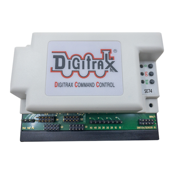
6.2 Program SE74 CVs on LocoNet:
DT602, press the; Menu>2>1 keys to enter Operations Mode programming.
1.
Press the "SWITCH" soft key F to enter
the "Ops Switch" mode programming
screen as shown adjacent. This example
screen shows CV11 selected for an SE74
with BASE address of SW1.
2.
Use the LH and RH encoder knobs to
select the SW#/ADR of the SE74 to
modify a CV on. An SE74's CV11 to
CV16 access the 48 OPSW bit settings.
3.
For example; press the "CVDATA" soft
key at CV11 to change to CV data entry,
press the number 1 then press "WRITE".
This now configures the 8 OPSW bits of
CV11 to 1, forcing this SE74 to change to
slow motion turnout control.
4.
Be careful changing the values in
CV11,12,13,14,15 and CV16 since the 8
bit data number 0-255 in these CV's ac-
tually each control 8 individual OPSW bits. OPSW1 is ls bit of CV11, through
OPSW8, as ms bit of CV11.
5.
The DT602 does not indicate to the SE74 when programming is complete.
After finishing CV changes, best practice is to POWER cycle the SE74 to save
changes. Alternately, you can WRITE CV7 to 00 to restart that SE74.
7.0 Signal head connections:
ics of the supplied PCB test mast and details for wiring up your signal heads.
1.
Figure 2 shows two SE1 cable sets to signal a siding. Figure 3 shows how
plug-in masts are oriented to access the A1/A2 or B/C heads on masts
plugged into a SE1 cable socket. On a layout B/C signals are sep-
arate masts/sockets. At right is an image of a PCB test mast >
Figure 2: Example of two security elements (SE1 cables) configured as a siding.
SE1 #1- left siding:
Figure3: Digitrax SE1 cable version for access to 4 plug-in heads
© 2022 Digitrax, Inc.
As for section 2.0, with a
CV Program Menu A:
Ops Switch ADR: 0001
CV Number:
CV data:
CVNUM
The following figures include schemat-
SE1 #2-right siding:
— 9 —
LOCO
0011
0000
CVDATA
DONE
www.digitrax.com
