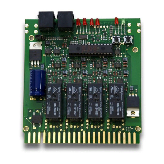
4.0 PM42 Wiring
(See TABLES I &II and Diagrams 1 & 2)
1. Before installing the PM42 on your layout, be sure that your boosters
shut down correctly when a short circuit occurs. To do this, short the
track in each power district. Use a coin or screwdriver blade across
the tracks in several locations within the district to create a short cir-
cuit. The booster in the shorted district should beep and shut down
each time you short the track, the other boosters and districts will
continue to run. Once the short is cleared, the booster that was short-
ed should automatically resume operation. If the booster does not
shut down as described, then more or heavier feeder wires or bus
wires may be necessary to correct this.
2. Connect the wires from the booster's Rail A & Rail B outputs to the
Rail A & Rail B inputs for one section of the PM42 that will be
powered by that booster. (See TABLES I & II for connection
details for each PM42 section). You can use a different booster to
drive each of the PM42's four sections if desired.
3. Wire at least one of the PM42's ground connections (Pin B or X) to
the Digitrax booster ground, common (or case) of the boosters.
4. Wire the PM42's Track Outputs A&B to the A&B rails of the track to
be controlled.
5. To make a PM42 section "AutoReversing" first, connect the "REV"
pins and adjacent "TRACK OUTPUT" pins on the 44 -pin connector
for that PM42 section as shown in Diagrams 1 & 2. Then, set the
related op switch (OpSw) for Auto-reversing. (See TABLE III for
OpSw number). See Section 5.0 PM42 OpSw Set Up.
6. Connect a 12-18V AC or DC power supply to the AC1 (Pin 3) and
AC2 (Pin C) terminals of the 44-pin connector. This powers the
PM42(s). Multiple PM42s can be supplied by a single power supply
as long as you provide 125mA for each PM42. This supply should
not power or be shared by any devices other than PM42s.
Tracks should be double gapped between adjacent power districts.
Be sure the 44-pin connector is plugged in to the PM42 with the numbered pin
labels on the component side of the board. (See PM42 Top View on Front
Cover of this manual).
4
