- ページ 5
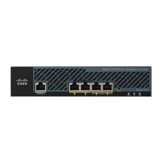
サーバー Cisco 2500 SeriesのPDF 設置マニュアルをオンラインで閲覧またはダウンロードできます。Cisco 2500 Series 12 ページ。 Wireless controller
Cisco 2500 Series にも: 設定マニュアル (19 ページ), 配備マニュアル (23 ページ), 設定マニュアル (50 ページ), スタートマニュアル (47 ページ)

Figure 4
Step 4
Installing AC and DC Power Supplies
This section describes how to install AC and DC power supplies. Although an AC power supply is
shown in the illustrations that follow, the procedure is the same for installing both AC and DC power
supplies.
Step 1
Figure 5
Step 2
Removing the Power Supply
AC power supply
Place the removed screw and power supply in an antistatic bag.
Put the power supply into place and gently slide it toward the back of the chassis engaging
the tabs on the bottom of the case with the slots in the bottom of the power supply.
(See Figure 5.)
Inserting the Power Supply
T oken Ring Switch
0
1
2
3
4
5
6
7
8
Stations
T oken Ring Switch
0
1
2
3
4
5
6
7
8
Stations
Install the screw that came with the Cisco power supply into the screw hole between the
power switch and power connector. (See Figure 6.)
Fan
T oken Ring Switch
9
0
1
2
3
4
Stations
T oken Ring Switch
Patch
cables
9
0
1
2
3
4
Lobe
cables
Stations
Installing Cisco AC and DC Power Supplies in Cisco 2500 Series Routers
Installing AC and DC Power Supplies
5
6
7
8
9
5
6
7
8
9
5
