- ページ 3
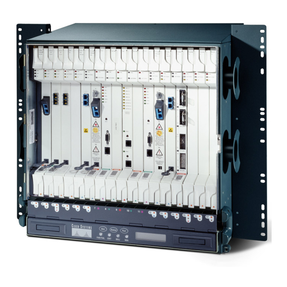
サーバー Cisco ONS 15454のPDF インストールをオンラインで閲覧またはダウンロードできます。Cisco ONS 15454 32 ページ。 Four-shelf and zero-shelf bay assembly
Cisco ONS 15454 にも: 取付説明書 (22 ページ), インストール (32 ページ), 開梱と設置 (42 ページ), 開梱と設置 (40 ページ)

Chapter 1 Install the Shelf and Backplane Cable
•
The following materials are required to install the optional air ramp. The number in parentheses gives
the quantity of the item included in the package:
•
•
User-Supplied Materials
The following materials and tools are required but are not supplied with the ONS 15454:
•
•
•
•
•
•
•
•
•
•
•
•
•
Tools Needed
The following tools are needed to install an ONS 15454:
•
78-18537-01
Four 1 3/8-inch standoffs (50-1492-01)
–
Eight 2-inch standoffs (50-1453-01)
–
Four flathead screws, 6-32 x 0.5 (48-2116-01)
–
Standoff kit (53-0795-XX):
Plastic fiber management guides (2)
–
Fan filter bracket screws (53-48-0003) (6)
–
M4.0x 8mm, SS pan-head Phillips mounting screws (2)
Mounting brackets, 19 inch (482.6 mm), 23 inch (584.2 mm) (2)
One or more of the following equipment racks:
19-inch ANSI Standard (Telcordia GR-63-CORE) (482.6 mm) rack; total width 22 inches
–
(558.8 mm)
23-inch ANSI Standard (Telcordia GR-63-CORE) (584.2 mm) rack; total width 26 inches
–
(660.4 mm)
Fuse panel
Power cable (from fuse and alarm panel to assembly), #10 AWG, copper conductors,
194 degrees Fahrenheit (90 degrees Celsius)
Ground cable #6 AWG stranded
Alarm cable pairs for all alarm connections, #22 or #24 AWG (0.51 mm² or 0.64 mm²), solid tinned
100-ohm shielded building integrated timing supply (BITS) clock cable pair #22 or #24 AWG
(0.51 mm² or 0.64 mm²), twisted-pair T1-type
Single-mode SC fiber jumpers with UPC polish (55 dB or better) for optical (OC-N) cards
Shielded coaxial cable terminated with SMB or BNC connectors for DS-3 cards
Shielded ABAM cable terminated with AMP Champ connectors or unterminated for DS1N-14 cards
with #22 or #24 AWG (0.51 mm² or 0.64 mm²) ground wire (typically about two ft [61 cm] in length)
6-pair #29 AWG double-shielded cable
Tie wraps and/or lacing cord
Labels
Listed pressure terminal connectors, typically dual lug type; connectors must be suitable for #6
AWG copper conductors with stud size and spacing per equipment rack specifications; connection
to office ground typically through H-TAP compression connector, according to site practice
#2 Phillips screwdriver
Cisco ONS 15454 Procedure Guide, Release 8.5.1
User-Supplied Materials
1-3
