- ページ 11
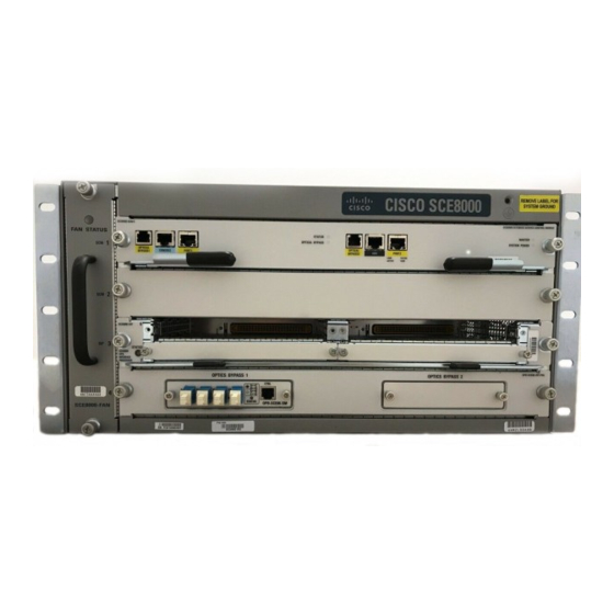
サーバー Cisco SCE8000 GBEのPDF クイック・スタート・マニュアルをオンラインで閲覧またはダウンロードできます。Cisco SCE8000 GBE 25 ページ。 10gbe platform
Cisco SCE8000 GBE にも: 設定マニュアル (18 ページ), 取り外しと交換の手順 (36 ページ), インストール (21 ページ)

Installing an AC-Input Power Supply
Warning
This product requires short-circuit (over current) protection to be provided as part of the building installation.
Install only in accordance with national and local wiring regulations.
Ensure that the system (earth) ground connection is made. For ground connection instructions, see the
Step 1
Chassis Ground" section on page
Verify that the power switch is in the Off (0) position.
Step 2
Step 3
Plug the power cord into the power supply.
Connect the other end of the power cord to an AC-input power source.
Step 4
Caution
In a system with dual power supplies, connect each power supply to a separate input source. In case of a power
source failure, the second source will most likely still be available.
Step 5
Turn the switch on the power supply to the On (|) position.
Verify power supply operation by checking the power supply LEDs. The power supply LEDs should be in the following
Step 6
states:
• Input OK LED is green
• Fan OK LED is green
• Output Failed LED is not lit
If the LEDs indicate a power issue, see the
4
Connecting Management Interfaces and Performing Initial System
Configuration
This section explains how to connect the SCE 8000 platform to a local console and how to cable the Gigabit Ethernet
management interface.
Connecting the Local Console
You must first connect the unit to a local console and configure the initial settings for the SCE8000 to support remote
management.
Make sure that the terminal configuration is as follows:
• 9600 baud
• 8 data bits
• No Parity
• 1 stop bits
• No flow control
The above Cisco SCE8000 port parameters are fixed and are not configurable.
Step 1
Plug the RS-232 serial cable provided with the Cisco SCE 8000 into the Con port on the front panel of the
SCE8000-SCM-E (item #2 in
6.
"Identifying Startup Issues" section on page
Figure
8).
"Connecting the
23.
11
