- ページ 6
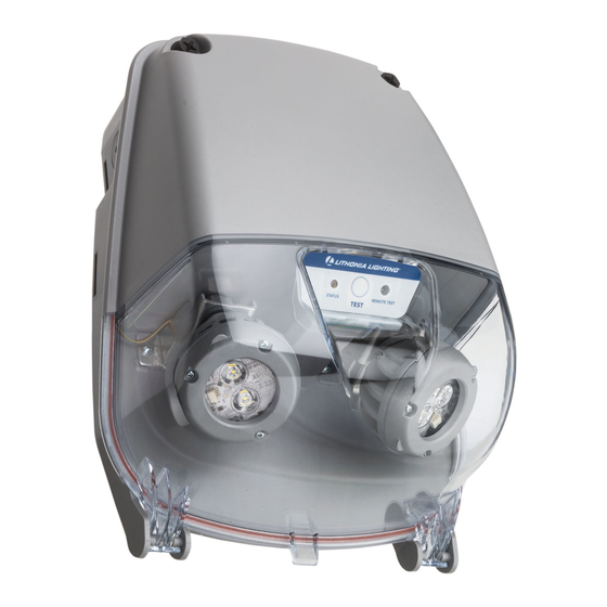
照明器具 Acuity Brands EXTLのPDF マニュアルをオンラインで閲覧またはダウンロードできます。Acuity Brands EXTL 20 ページ。 Emergency lighting unit

LAMP REPLACEMENT
With unit open, disconnect
1
the lamphead harness from
the charger board. Refer to
wiring diagram from page 6.
for lamphead connectors on
charger board.
Screw
CHARGER BOARD REPLACEMENT
Lift charger board tray and open
1
dielectric cover. Disconnect all
harnesses connected to the charger
board.
Dielectric
Cover
MAINTENANCE
Remove lamphead bracket from the
2
housing by removing two screws.
Remove the nut and washer from
the lamphead and carefully remove
the lamphead from the bracket.
Nut
Washer
To remove the charger board from tray
2
release snaps (5x) and remove. To
install new charger board place over
snaps in correct orientation with dielectric
cover installed under the charger board
as shown. Press down firmly until snaps
engage.
To reinstall lamphead, route harness
3
through bracket, washer and nut and then
tighten nut down a ¼ turn after the gasket
begins to compress. Attach the lamphead
bracket to the housing and then connect
lamphead harness to charger board (see
page 6 for wiring diagram).
Gasket
Reconnect all harnesses and position the
3
end of the charger board tray onto guide
rails and push down until you hear a
"snap". Route wires along the side of the
guide rail to avoid wires from pinching.
Battery harness must be routed through
flap in dielectric cover.
Snaps
Tray
Charger board
page 5
Screw
Battery harness
routing location
