- ページ 24
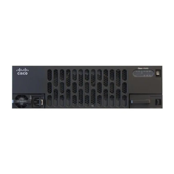
ゲートウェイ Cisco 450のPDF ハードウェア・インストール・マニュアルをオンラインで閲覧またはダウンロードできます。Cisco 450 37 ページ。 Voice gateway

Removing Cisco VG450 Voice Gateway
3. Align the module with the guides in the chassis walls or slot divider and slide it gently into the NIM slot
on the router.
4. Push the module into place until you feel the edge connector seat securely into the connector on the router
backplane. The module faceplate should contact the chassis rear panel.
5. Using a number 1 Phillips or flat-blade screwdriver, tighten the captive screws on the service module.
6. Connect the module to the network and reenable the power to the slot in the router.
DETAILED STEPS
Step 1
Shut down the electrical power to the slot in the router either by turning off the electrical power to the router or by issuing
the online insertion and removal (OIR) commands. Leave the power cable plugged in to channel ESD voltages to ground.
For more information on OIR, see the "Managing Cisco Enhanced Services and Network Interface Modules" chapter in
the Cisco 4000 Series ISRs Software Configuration Guide .
Step 2
Remove the blank faceplates installed over the network interface module slot that you intend to use.
Save blank faceplates for future use.
Tip
Step 3
Align the module with the guides in the chassis walls or slot divider and slide it gently into the NIM slot on the router.
Step 4
Push the module into place until you feel the edge connector seat securely into the connector on the router backplane.
The module faceplate should contact the chassis rear panel.
Step 5
Using a number 1 Phillips or flat-blade screwdriver, tighten the captive screws on the service module.
Step 6
Connect the module to the network and reenable the power to the slot in the router.
Removing Cisco VG450 Voice Gateway
SUMMARY STEPS
1. Shut down the electrical power to the slot in the router either by turning off the electrical power to the
router or by issuing the online insertion and removal (OIR) commands. Leave the power cable plugged
in to channel ESD voltages to ground. For more information on OIR, see the "Managing Cisco Enhanced
Services and Network Interface Modules" chapter in the Cisco 4000 Series ISRs Software Configuration
Guide .
2. Using a number 1 Phillips or flat-blade screwdriver, loosen the captive screws on the NIM.
3. Slide the service module out.
DETAILED STEPS
Step 1
Shut down the electrical power to the slot in the router either by turning off the electrical power to the router or by issuing
the online insertion and removal (OIR) commands. Leave the power cable plugged in to channel ESD voltages to ground.
For more information on OIR, see the "Managing Cisco Enhanced Services and Network Interface Modules" chapter in
the Cisco 4000 Series ISRs Software Configuration Guide .
Step 2
Using a number 1 Phillips or flat-blade screwdriver, loosen the captive screws on the NIM.
Step 3
Slide the service module out.
Cisco 450 Voice Gateway Hardware Installation Guide
22
Installing the Cisco VG450 Voice Gateway
