- ページ 12
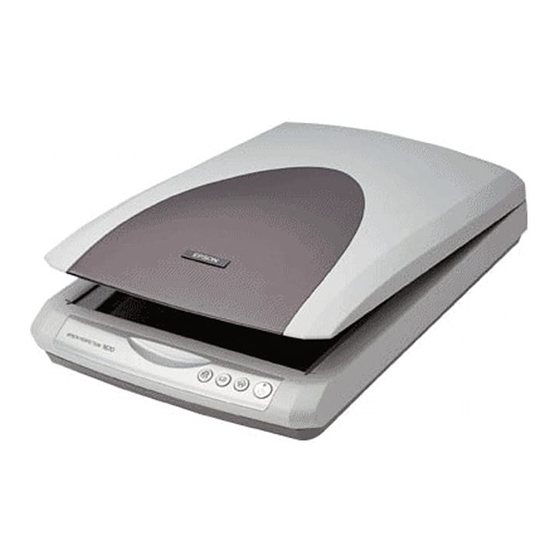
スキャナー Epson Perfection 1670 PhotoのPDF サービスマニュアルをオンラインで閲覧またはダウンロードできます。Epson Perfection 1670 Photo 46 ページ。 Color image scanner
Epson Perfection 1670 Photo にも: 製品情報 (7 ページ), スタートマニュアル (9 ページ), マニュアル (11 ページ), 更新 (1 ページ), 製品サポート速報 (17 ページ), 製品サポート速報 (12 ページ), 重要な安全上のご注意 (4 ページ), パンフレット&スペック (2 ページ)

EPSON Perfection 1670 Photo/Perfection 1270
2.1 Overview
This chapter explains the procedures for disassembling the major units and parts of the
product. Unless otherwise explained, reassembly should be carried out in the reverse
order of the disassembly procedure. When you have to remove any units or
components that are not described in this chapter, refer the exploded diagram in the
Appendix.
Before starting disassembly, always read the precautions described in the next section.
2.1.1 Precautions
Before starting the disassembly or reassembly of the product, always read the
following precautions given under the headings "WARNING" and "CAUTION".
Before disassembling or reassembling this product, always
W A R N I N G
disconnect the Power Cable and Interface Cable. However,
when you have to work with power ON for voltage
measurement, etc., use extreme care not to get an electric shock
and do the work in accordance with the procedure given in this
manual.
To prevent your hands from being cut by sharp edges, always
wear gloves before starting disassembly/reassembly.
When touching any internal components, use a static electricity
discharger such as anti-static wrist straps, and handle them
carefully to protect the microprocessors and circuits.
When transporting this product, always make sure that the
C A U T I O N
Carriage has returned to the home position (front), and lock
the Carriage Unit.
Provide sufficient work space for disassembling and
reassembling.
Always use only the recommended tools for disassembly,
reassembly and adjustment.
Be sure to tighten the screws to the specified torque.
Use the specified grease for lubrication. (Refer to Chapter 4 for
details.)
DISASSEMBLY/ASSEMBLY
The following figure shows the definition of the scanner orientations explained in the
disassembly procedure.
Figure 2-1. Orientation Definition
2.1.2 Used Tools
To protect this product from damage, use the specified tools indicated in the following
table.
Tool Name
Phillips screwdriver No. 1
Phillips screwdriver No. 2
Flat-blade screwdriver
Long-nose pliers
Tweezers
Overview
Table 2-1. Specified Tools
Supplier
Part Number
EPSON
1080530
EPSON
1080532
EPSON
1080527
EPSON
TBD
EPSON
1080561
Revision B
12
