- ページ 15
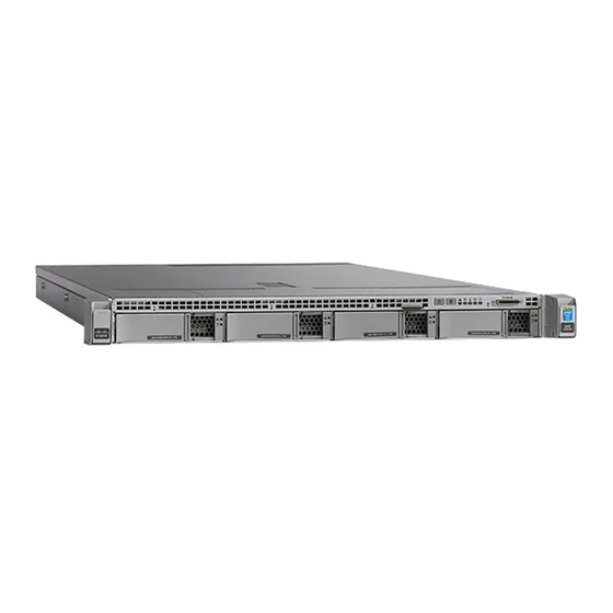
ゲートウェイ Cisco Firepower 4600のPDF ハードウェア・インストール・マニュアルをオンラインで閲覧またはダウンロードできます。Cisco Firepower 4600 44 ページ。

Overview
7
9
11
13
Rear Panel LEDs
The following figure shows the rear panel LEDs and describes their states.
Figure 9: Rear Panel LEDs and Their States
1
Serial console port (RJ-45 connector)
Disabled by default; use the VGA port
and keyboard USB port instead. See
the "Set up Serial Access" topic in the
Cisco Firepower Management Center
Getting Started Guide for Models
1600, 2600, and
4600.
770-W AC power supply (PSU 1)
Threaded holes for dual-hole
grounding lug
eth3 management interface
10-Gigabit Ethernet SFP+ support
Use only Cisco-supported SFP+
transceivers.
100-Mbps/1-Gbps/10-Gbps Ethernet
link (speed on both LAN1 and LAN2):
• Off—Link speed is 100 Mbps.
• Amber—Link speed is 1 Gbps.
• Green—Link speed is 10 Gbps.
Cisco Firepower Management Center 1600, 2600, and 4600 Hardware Installation Guide
8
Unit identification button
10
770-W AC power supply (PSU 2)
12
eth2 management interface
10-Gigabit Ethernet SFP+ support
Use only Cisco-supported SFP+
transceivers.
14
Riser handle
Not in use
2
100-Mbps/1-Gbps/10-Gbps Ethernet
link status (speed on both LAN1 and
LAN2):
• Off—No link is present.
• Green—Link is active.
• Green, flashing—Traffic is
present on the active link.
Rear Panel LEDs
11
