- ページ 12
ゲートウェイ Cisco S695FのPDF スタートマニュアルをオンラインで閲覧またはダウンロードできます。Cisco S695F 18 ページ。 Web security appliance
Cisco S695F にも: マニュアル (24 ページ), ハードウェア・インストール・マニュアル (50 ページ)

Connect to the Appliance
Cisco S695F Appliance
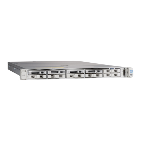
The following illustration shows the Cisco S695F model with fiber optic ports. These fiber optic ports
are located above the Ethernet ports shown in the illustration, and the Ethernet ports are not present.
For details, see the
The top two fiber optic ports are used as proxy ports in the same way as the Ethernet proxy ports
described in the following table. The middle two fiber optic ports are used as traffic ports. The bottom
two fiber optic ports are used as Management ports.
Plug one end of each straight power cable into the redundant power supplies on the back panel of the
Step 1
appliance.
Plug the other end into an electrical outlet.
Step 2
Plug the Ethernet cables into the appropriate ports on the back panel of the appliance.
Step 3
•
•
Step 4
Connect your laptop to the Management port using the Ethernet cable included in the system box.
Use only the transceiver modules supplied with the 10-Gigabit fiber optic interfaces. The use of any
Caution
other transceiver modules may damage the fiber optic interface card.
Cisco Web Security Appliance S195, S395, S695, and S695F Getting Started Guide
12
Cisco x95 Series Web Security Appliances Installation and Maintenance
The proxy ports are labeled P1 and P2.
P1 only enabled: When only P1 is enabled, connect it to the network for both incoming and
–
outgoing traffic.
P1 and P2 enabled: When both P1 and P2 are enabled, you must connect P1 to the internal
–
network and P2 to the Internet.
The traffic monitor ports are labeled T1 and T2.
Simplex tap: Ports T1 and T2; one cable for all packets destined for the internet (T1) and one
–
cable for all packets coming from the internet (T2).
Duplex tap: Port T1; one cable for all incoming and outgoing traffic.
–
Guide.
