- ページ 3
モニター Crowcon Gasman IIのPDF 技術説明をオンラインで閲覧またはダウンロードできます。Crowcon Gasman II 18 ページ。 Portable gas detector

Functional Description
2
System Overview
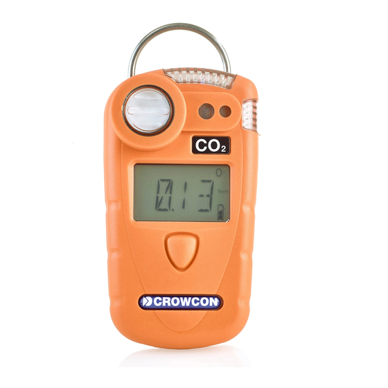
The GasmanII Portable Gas Detector system is designed to detect the presence of toxic or flammable gases or the
absence of life supporting gases. As an option it may be fitted with a low power transmitter PCB to permit the use of a
body-worn Vibrating Pager Unit.
The standard GasmanII Portable Gas Detector monitors the level of a particular gas in the atmosphere and provides both
an audible and a visual alarm should the gas levels become unacceptable. When fitted with the optional low power
transmitter PCB the unit also emits a 418MHz RF carrier wave that is 'On-Off-Key' (OOK) modulated at about 10Hz. It is
this signal, which is only emitted while the alarm condition exists, that the GasmanII Vibrating Pager Unit intercepts and
produce a pulsing vibration to augment the audible and visual alarms provided by the GasmanII Portable Gas Detector.
Gasman II Block Diagram
The circuit consists of the functional blocks as shown in Figure 1 below and a complete unit is assembled from 3 PCBs,
with an optional fourth PCB, as shown in the appendices. Each of the three distinct gas types requires a specific type of
gas sensor, signal conditioning circuitry and calibration information. All of the gas sensors share a similar mechanical
design and are plugged into a small daughter board at the top of the unit. The output signal from the various types of
sensor is different and each requires a corresponding signal conditioning amplifier to interface the signal to the common
CPU section. The calibration information is stored in non-volatile memory within the unit and is factory set.
The CPU is powered in a low-power state at all times that batteries are present and controls the electronic switch to apply
power to the rest of the circuitry when one of the front-panel mounted buttons is pressed. Once powered the unit
continuously monitors the gas level comparing it with preset alarm levels and, should an alarm level be exceeded, the
buzzer and the LED operate to provide both audible and visual warnings. The two signals that drive the LEDs are
combined on the optional low-power transmitter PCB to form a 10Hz signal that is used to modulate an RF Monolithics
transmitter module.
electronic
switch
LCD display
buzzer
gas
analogue
cpu
sensor
signal conditioning
(ROM & RAM)
LEDs
low
power
txmtr
(optional)
Figure 1: Gasman II Block Diagram
