- ページ 14
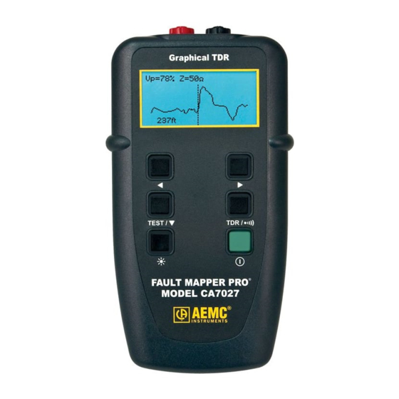
計測機器 AEMC instruments CA7027のPDF ユーザーマニュアルをオンラインで閲覧またはダウンロードできます。AEMC instruments CA7027 20 ページ。 Fault mapper pro graphical tdr
AEMC instruments CA7027 にも: ユーザーマニュアル (20 ページ)

1. Take a cable sample of exact length increments (ft or m) longer than
300 ft (100m).
2. Measure the exact length of the cable using a tape measure.
3. Connect one end of the cable to the Fault Mapper Pro
end unterminated and make sure the wires do not short to each
other.
4. Measure the length and adjust the Vp until the exact length is displayed.
5. When the exact length is displayed, Vp is established.
4.10 Attaching a Cable to the Fault Mapper Pro
1. Check that the far end of the cable is either open or shorted (not
fitted with a resistive termination).
2. Attach the Fault Mapper Pro
The cable attachment is via a banana plug input located at the top of the
unit. For unterminated cables use the alligator clip attachment provided.
Coaxial Cable:
Shielded Cable: Connect the Red clip to a wire adjacent to the
Twisted Pair:
Multi-conductor Cable: Connect the clips to any two wires.
12
Find Quality Products Online at:
WARNING: Make sure that there is no power supply or equipment attached
to the cable to be tested.
Connect the Red clip to the center wire and the
Black clip to the shield/screen.
shield and the Black clip to the shield.
Separate out one pair and connect the red and black
clips to the two wires of the pair.
GlobalTestSupply
www.
®
to one end of the cable to be tested.
Fault Mapper Pro
.com
®
. Leave the
®
®
Model CA7027
