- ページ 33
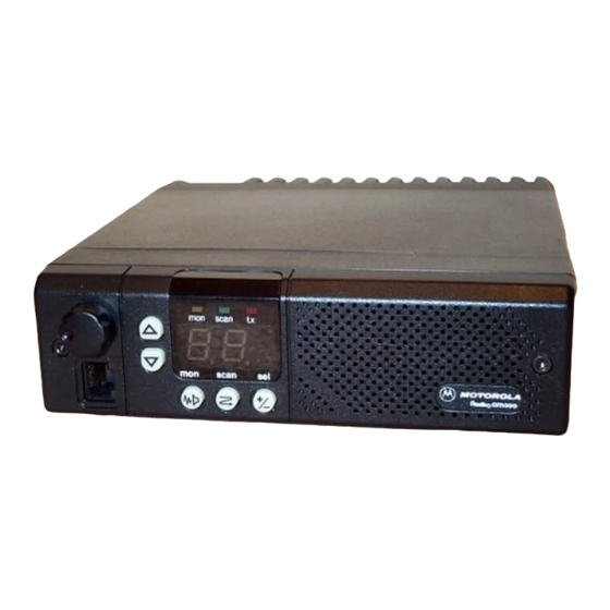
ラジオ Motorola RADIUS GM300のPDF サービスマニュアルをオンラインで閲覧またはダウンロードできます。Motorola RADIUS GM300 49 ページ。 16-channel, conventional fm radio
Motorola RADIUS GM300 にも: サービスマニュアル (28 ページ), 取扱説明書 (18 ページ), 取扱説明書 (19 ページ), ユーザーマニュアル (37 ページ), 操作説明 (2 ページ)

Theory of Operation
Logic Board
The microcomputer puts the address information on
AD0-AD7 and the information is then passed to U803.
The address strobe ÒASÓ is pulsed low and the byte is
latched. The de-multiplexed address byte A0-A7 is
then available on U803. The bus is now ready for the
transmission of data. The higher order address byte
A8-A15 is not multiplexed and is readily available at
the microcomputer U802.
Reading or Writing in Memory-Expanded Logic
In expanded logic boards, the speciÞed memory IC
must Þrst be enabled before a read/write operation can
take place. Each memory IC has its own chip select line.
EPROM SEL originates at U803- 13, EEPROM SEL at
U803-14, and SRAM SEL at U803-15. The lines are nor-
mally logic high; a speciÞc IC is selected when the
appropriate line is pulsed low.
The R/W line from U803-16 determines if data is being
read (logic high) or written (logic low). EPROM U804
is a read-only memory and does not require a R/W
input.
The output enable line ÒOEÓ, when pulsed low, will
enable the tri-state output gates to pass the contents of
the desired address out onto the A/D bus.
Programmable I/O's
In masked logic boards, the function of J3-14 is pro-
grammable by the placement of push-on jumper
JU809. In the ÒREMOTEÓ position, J3-14 provides the
hook function for a remote desk set. When pulled low,
the radio is forced Òoff-hookÓ or into a monitor condi-
tion. In the ÒPAÓ position, J3-14 provides the public
address enable function; when pulled low, transmitter
PTT is inhibited.
In expanded logic boards, pins 8, 12 and 14 are soft-
ware- programmable I/OÕs, pins 6 and 9 are software
programmable inputs, and pin 4 is a software-pro-
grammable output. If, for example, J3-14 is used as an
input, U803-39 will be logic low, keeping Q814 off.
When an accessory pulls J3-14 low, Q813 will turn off,
and the resulting logic high at its collector will be read
by U803-24. If J3-14 is programmed as an output, the
signal provided by U803-39 will turn Q814 on or off as
needed, supplying either an active low or a logic high
(pulled up by R901, 4.7k) to the accessory. By moving
JU808 from its normal PROG I/O position to the SCI+
position, J3-12 can be used as an SCI programming
line, electrically connected via J8-9 to the SCI+ pin on
the microphone connector (pin 7).
Receiver Audio
Voice Path
Detector audio from the RF board is routed via J6-3 to
U551A. A series resistor on the RF board, R62, is chosen
2-8
to provide an additional 6 dB of receiver audio gain in
12.5 kHz channel spacing models, where full system
deviation is one half of that used for 25/30 kHz chan-
nel spacing. The gain of U551A is chosen so that sup-
ply-rail limiting occurs at 20% above full system
deviation. This limits the amplitude of impulse-type
ignition noise. Noise above 3 kHz is attenuated by a 3-
pole low pass Þlter (U551B) whose Bessel-Thompson
characteristic is chosen to minimize ringing due to
impulse-type noise. Following is a 5-pole biquadratic
300 Hz high-pass Þlter (U552A and B) which attenu-
ates subaudible signaling tones such as PL and DPL.
This is followed by de-emphasis ampliÞer U553A,
mute gate Q551 and summing ampliÞer U553B which
combines the receive audio signal with alert tones gen-
erated by the microcomputer at U802-29 and Þltered
by C566 and C567. The output of U553B is routed to the
volume control via J8-1, from the volume control via J8-
2 to the input of the audio power ampliÞer, U501.
The audio power ampliÞer is a BTL (bridge-tied load)
conÞguration providing 7.5 watts rms into an external
8 ohm speaker. Both sides of the speaker are driven
with out-of-phase signals, therefore neither side of the
speaker can be grounded. The outputs are internally
protected against accidental short circuits to supply or
ground. The internal speaker has a 22 ohm impedance
which limits the power delivered to it to 3 watts, which
is within its rating. The audio power ampliÞer is
turned on when a sense voltage greater than 8 volts DC
is applied to pin 8. This is obtained from SW B+ via
R501. When no audio output is required, U501 is
turned off by saturating transistor Q501, providing 0
volts to U451 pin 8. This allows muting of the audio
power ampliÞer. When the radio is turned off, SW B+
is not present, so there is no source of voltage to pin 8
via R501, keeping U501 off. When muted (pin 8 low),
U501 draws no current from the UNSW B+ source.
Capacitor C504 controls the turn on and turn off timing
of the power ampliÞer to minimize transients. C501
and C502 provide low and high frequency Þltering
respectively.
When any front panel button is pressed, a beep is heard
in the speaker. This is produced by the microcomputer-
generated alert tone applied to stage U553B, as dis-
cussed above. U501 is enabled by turning off Q501,
however mute gate Q551 remains muted so that the
beep is heard but noise or signals from the receiver are
not. Alert tones are also used by various signaling sys-
tems, or for error tones during self-test.
Receiver audio is available at the accessory connector
J3-11. Depending on the position of push-on jumper
JU551, audio may be either de-emphasized, Þltered
and muted, derived from the output of U553B, or ßat
and unmuted, derived from the output of U551A in
masked logic boards or from buffer U651B in expanded
logic boards.
68 No.
Name of Manual
March, 1997
