- ページ 25
ポータブルラジオ Motorola MTX450のPDF 基本サービスマニュアルの補足をオンラインで閲覧またはダウンロードできます。Motorola MTX450 44 ページ。 Professional portable radio
Chapter 4
Transceiver Performance Testing
For the missing sub-sections in this chapter, please refer to Basic Service Manual 68P80906Z54.
4.1
RF Test Mode
When the radio is operating in its normal environment, the radio's microcontroller controls the RF
channel selection, transmitter key-up, and receiver muting. However, when the unit is on the bench for
testing, alignment, or repair, it is removed from its normal environment and cannot receive commands
from its system. Therefore, the internal microcontroller does not key the transmitter or unmute the
receiver. This prevents the use of a normal tuning procedure. To solve this problem, a special "test
mode" is incorporated into the radio.
Note 1: On UHF, LTR models, the radio must be in either conventional or LTR mode.
Note 2: The test mode procedure that follows assumes that the Customer Programming Software
Front Panel Access screen has both the FPA and RF TEST boxes selected. Select from the
programming screen to enable or disable certain features of the radio RF test mode.
FPA entry not selected blocks all test modes.
FPA entry selected and RF TEST not selected blocks RF test mode.
FPA entry selected and RF TEST selected enables all test modes.
To enter the test mode for a display radio:
1. Turn the radio on.
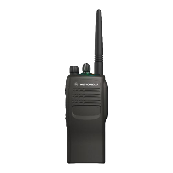
2. Within ten seconds after the self test is complete, press 'side button 2', shown in Figure
4-1, five times in succession.
3. After "CSQ CHXX SP25" appears on the display, the radio is on channel XX (see Note
on following page), carrier squelch mode, 25 kHz channel spacing. Each additional
press of 'side button 2' (see Table 4-2) scrolls to the next channel spacing, and a corre-
sponding set of tones are sounded. Refer to Figure 4-2 for test mode information for a
two-line display radio.
4. Press 'side button 1' to scroll through the test environments listed in Table 4-1 in Basic
Service Manual 68P80906Z54.
5. Press 'side button 2' for 3 seconds to switch the radio to the control head test mode.
'LCD Test' appears on the display.
6. Press 'side button 1' to turn on all the dots of the first character. Another 'side button 1'
press turns on all the dots of the next character, continuing until the last character is
reached.
7. Press 'side button 1' at the end of the LCD test to activate the 'Icon Test'. The next 'side
button 1' press turns on the first icon.
8. Press 'side button 1' at the end of the Icon Test to activate the button test. Pressing any
side button (except 'side button 1'), or any keypad button during the LCD test or Icon
test immediately activates this test. A good button press is verified by a chirp.
9. Press 'side button 2' for 3 seconds in the control head test mode to return the radio to
the RF Test mode.
4-1