- ページ 7
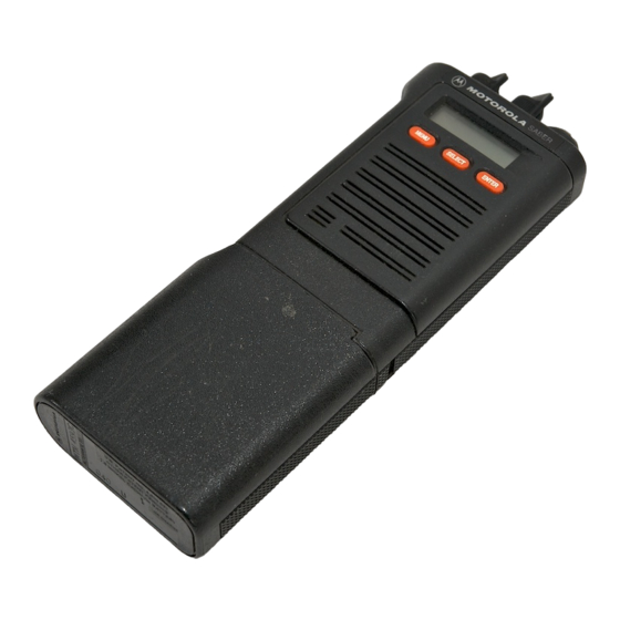
ポータブルラジオ Motorola SABER RのPDF サービスマニュアルをオンラインで閲覧またはダウンロードできます。Motorola SABER R 29 ページ。

E. With the
speaker facing
upward,
remove the
speaker bracket assembly
by
inserting
a thin
screwdriver blade between the frame and the
bottom
of
the
speaker bracket,
and prying gently upward
on
the
speaker bracket
until
it
is
disengaged
from
the frame.
FRONT SHIELD
ASSEMBLY
SPEAKER
SPEAKER
BRACKET
MAEPF-20612-0
F.
Lift the speaker bracket assembly away
from
the
bottom of
the frame
assembly,
then
pull
it
out from under
the plastic top panel. Be careful not to
pull
against the
flexible circuits connecting the
speaker bracket
to the
frame assembly.
MAEPF-20613-0
G.
ON
SABER
II
AND Systems
SABER
RADIOS
ONLY: Disconnect
the
LCD interconnect flexible
circuit
from the
frame
assembly
by pulling the header
straight
out and
away
from the main printed
circuit
board.
LCD
FLEXIBLE
t
CIRCUIT
HEADER
FRAME
MAEPF-20614-0
H.
Disconnect
the speaker/microphone
flexible
circuit
from
the frame
assembly by
pulling the
connector
straight
out and
away
from
the main printed circuit
board.
HEADER
FRAME
ASEMBLY
SPEAKER/MICROPHONE
FLEXIBLE CIRCUIT
MAEPF-20615-A
TOP PANEL
SPEAKER
BRACKET
QD
Mf
(
<
FLEXIBLE
u
\
CIRCUIT
ASSEMBLY
CAUTION
Refer
to
"SERVICING MAJOR SUBASSEM-
BLIES* (Section
2} and the appropriate exploded
view diagrams
at the
back
of
this manual before
attempting further
disassembly
or repair
ASEMBLY
4
