- ページ 7
モニター MSI MSI-8000HDのPDF 取扱説明書をオンラインで閲覧またはダウンロードできます。MSI MSI-8000HD 48 ページ。 Rf remote display

3
F3
PRINT
2
F2
F1
1
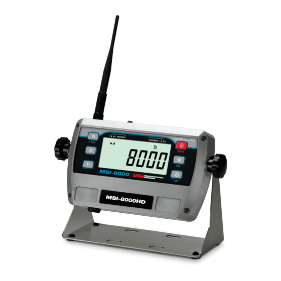
1.2 Front Panel Descriptions
Item No
1
F1 Key – Programmable to user selectable functions, see Section 3.0.
Default – Peak Hold.
Functions as the ENTER/SELECT key when in setup menus
2
F2 Key – Programmable to user selectable functions, see Section 3.0.
Default – Display & Function Test
Functions as the scroll key in setup menus
3
PRINT Key – Defaulted to the Print function.
4
CENTER-OF-ZERO Annunciator – Indicates the load is within 1/4d of
zero.
5
STABLE Annunciator – indicates that the load force has settled within the
motion window (usually ±1d).
When this symbol is off, the Scale / Dyna-Link will not zero, tare, or totalize.
6
F1 F2 LED – These blue LEDs are used to indicate various operational
features of functions programmed into the F1 and F2 keys.
Example:
In Peak Hold mode the associated LED will blink whenever a new peak
reading is captured.
7
Units and Load Annunciators
TOTAL (Ttl) Annunciator – Indicates the RF Linked Device is displaying the
Total accumulated weight. This is a temporary display lasting less than 5
seconds.
PEAK (Pk) Annunciator – Indicates the RF Linked Device is in the Peak
Hold mode.
NET (Net) Annunciator – Indicates the RF Linked Device is in the Net load
mode. A Tare weight is subtracted from the gross load.
METRIC TON (M) Annunciator – In conjunction with the Ton annunciator,
indicates the RF Linked Device is displaying Metric Tons.
TON (Ton) Annunciator – Illuminated alone, indicates the RF Linked Device
is displaying in US Short Tons (1 ton = 2000 lb.). When illuminated along
with the 'M' the RF Linked Device is displaying in Metric Tons (1 metric ton =
1000 kg)
6
5
1
2
FUNCTION
4
MSI-8000
Figure 1-1. MSI-8000HD Front Panel
7
SETPOINTS
10
Measurement Systems
International
Description
8
Class III/IIIL n
1
2
9
POWER
ZERO
14
TARE
TM
Introduction
=10000
max
11
12
13
3
