- ページ 2
エンクロージャー CRU DataPort DP10のPDF クイック・スタート・マニュアルをオンラインで閲覧またはダウンロードできます。CRU DataPort DP10 4 ページ。

2
DataPort DP10 Quick Start Guide
1 General Information
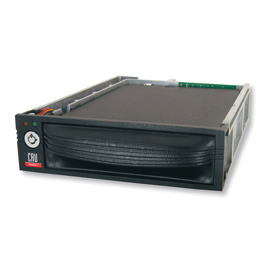
1.1 Identifying Parts
Status Lights
and Keylock
Frame
1.2 LED Behavior
LED
Color
Drive Power
Green
Drive Activity
Amber
2 Frame Installation
a. Slide the receiving frame into an open 5.25-inch bay.
b. Secure the receiving frame to the chassis with the four screws provided.
c. Attach a SATA data cable to the SATA port on the rear of the receiving frame and the other end to the
corresponding SAS or SATA port on the computer's motherboard.
d. Attach a SATA power connector from your computer to the SATA power port on the rear of the
receiving frame. If no SATA power connectors are available, attach the included Molex-to-SATA
adapter cable to a Molex power plug. Then plug the SATA end of the adapter cable into the rear of
the receiving frame.
Front
Carrier
State
Solid
The drive inside the carrier is powered on.
The fan on the rear of the receiving frame has failed. Please contact CRU
Blinking
Technical Support.
Blinking
The drive inside the carrier is being accessed by your computer.
Rear
SATA Power and
Data Connectors
Description
Cooling Fan
®
