- ページ 2
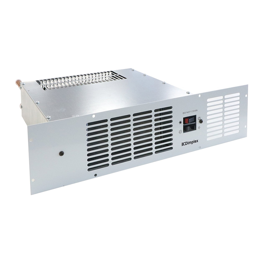
電気ヒーター Dimplex BUH19BWSのPDF 操作説明をオンラインで閲覧またはダウンロードできます。Dimplex BUH19BWS 4 ページ。 Hydronic base unit heater
Dimplex BUH19BWS にも: 設置および操作説明書 (4 ページ)

Central heating design system
1.
When fitting the appliance onto a central heating
system check that the boiler is capable of delivering
extra heat into the appliance by resizing the system.
The appliance will add an average of 2kW (6,830
Btu/Hr) onto the boiler sizing.
2.
Due to the low water content of the heat exchanger
in the appliance compared to a panel radiator
system, an adequate flow of water should be
maintained to compensate for rapid cooling of the
water as it passes through the exchanger i.e.
maximum efficiency is gained if the appliance is
placed as near to the boiler as possible to give the
maximum pressure head across the appliance.
Installation procedure
Ensure that all packing items are removed (read any warning
labels carefully). Retain all packing for possible use, in the
event of moving or returning the heater to your supplier.
Cutting the aperture in the plinth
Cut aperture in furniture unit plinth to dimensions shown.
This must be positioned so that the minimum distance from
the bottom of the aperture to the top surface of any floor
covering is not less than 12mm and not more than 25mm
(see Fig. 2).
If an overhang above the heater is greater than 75mm, then
a distance of at least 100mm must be maintained between
the overhang and the uppermost part of the heater.
Fig. 2
(all dimensions in mm)
Water Connections
WARNING: Do NOT connect electricity supply when making
water connections.
Connect the flexible pipes to the system flow and return
pipes.
The appliance terminates in 15mm pipe tails (top pipe flow –
bottom pipe return). Connect the valve ends of the flexible
pipe to the rear of the appliance. (Note: The direction of flow
arrows on the valves are not significant in this application.)
(see Fig. 3).
Fill and vent the system and bleed the air out of the heat.
exchanger using the bleed screw provided (located at the top
of the flow pipe).(see Fig. 4).
Close the vent and check the appliance for water leaks. If
any water escapes from the bleed screw ensure ensure it
does not fall onto any electrical wiring or connections. After
bleeding the appliance ensure that electrical controls are
completely dry before connecting to the power supply.
Power supply connection
WARNING: THIS APPLIANCE MUST BE EARTHED
This heater must be used on an AC~ supply only and the
voltage marked on the heater must correspond with the
supply voltage.
The installation of this appliance should be carried out by a
an electrician or competent person in strict accordance with
the current IEE Wiring Regulations and relevat Building
Regulations.
Before undertaking installation work, ensure the electricity
supply is disconnected from any relevant wiring.
The appliance is fitted with 2 meters of flexible cable 3 x
0.75mm² for electrical connection. The cable may be used to
connect the heater to the fixed wiring of the premises
through a suitable connection box. The supply circuit to the
heater must incorporate a double pole isolating switch having
a contact separation of at least 3mm. The power supply
cable should be routed through the plinth space to the
connection box, ensuring that the cable is left with enough
slack to allow removal of the appliance for maintenance. The
cable must be protected from any sharp edges.
Fitting the rear support bracket
The heater is supplied with a rear support bracket. Fit to the
back of the appliance with the two black screws supplied.
Adjust the rear support bracket so that the vertical distance
from the underside of the appliance to the bottom of the rear
support bracket equals the vertical distance from the floor in
the cupboard space to the bottom of the aperture opening.
The slots in the rear of the support bracket allow it to be
adjusted to the required height.
Fig. 3
Fig. 4
