- ページ 8
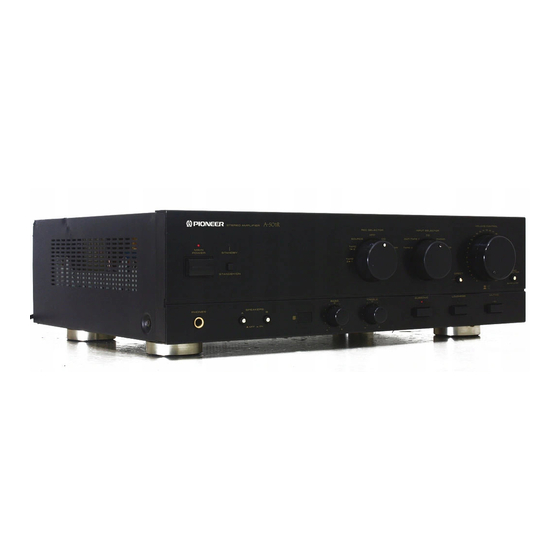
アンプ Pioneer A-550RのPDF サービスマニュアルをオンラインで閲覧またはダウンロードできます。Pioneer A-550R 28 ページ。
Pioneer A-550R にも: サービスマニュアル (27 ページ)

I¢101
UPC4570C (A-SSOR}
M5220P( A~450A)
Q203-208. 215-218.
2SA1048
Q305
Q231. 232
2Sat145
Q223. 224
2541306
Q229. 230. 233. 234.
2S5a992
Q238.
291-294
Q306
2SC1815
Q211- 212. 227. 228.
2SC1845
0237.
301. 302
Q10S.
106
2SC2458
{a-5SOR
ONLY}.
Q303. 304. 307
2SC2458
Q225. 226
2SC2603
219.
220
2SC2705
Q221. 222
2SC3298
Q101-104
2SK369.
{a-S50R
ONLY!
FUSE
assembly
MITCHEO
= SWITCHED
OOw MAX © 200W MAX
APOWER TRANSFORMER
cs
Ti
aTS1368(A~550R)
9, 12199
~~~ ATS1367(474508)
0. 047/400
134
A=450R/HE I}
1
0507
osse20F
0217-220
RO1SESB
(a-550R)
moe. 2881
pes
TD)
A-450R)
*
Ry303-:
6239
0201. 202
RD2. 7ESB4
1 ARESS Zia"
@}']
0307
AD22ESB
:
(a-550A}
'
Sate
AO15ESB
'
o3e0
©
{a-450R)
y
100
G)
D104. 102
RD7. SESB2
wo! Gvaoime
(A-550R ONLY)
D103
188252
(A~550R ONLY].
%
0209-216. 301-306 1SSa52
pyzoa-s
1 S388,
ASAI037
7100
ASA103618
Hoop
7100
RY302-2
3301iw)
R403
AY303-1
EYE
LEO
assembly
AXX1010
assembly
|
AatT1015,
ll.
Fy
3
3
es
AR 99999
oo)
ARBeaOG
baa pata
ac)
ee
Iay |
(ZRELE)
ROTARY
FUNC.
* $901-2
becomes
open
when
SS01-1
not
connect
to
any
contact
INPUT SELECTOR
$901
assembly
CONTROL
sssembiy (AW25496)
nso: &
330(1w)
rN
Bolo
R902
aa
eit
R304 100K
|
ay
SOS 100k
100K
10
SS
oe
Gn
eee
Ne
822
agg jo
ver
| So
eres
|
R970
100k
| So
eres
|
OPEN. when
starting
(Large
torque!
8
S791!
C918}
270p|
ae:
a
G
ee ee
Ic902-ICS904:MOTOR
DRIVER
Q903. ag04:
vre
SELECTION
FOR
CHARGING
MOTOR
FORCE
za
@909:a922 DRIVER
oad
ae eae same soe seas cea ak Deane reese enna
seer ee aeeee
a
rnd
Ee
eae
a
5078s
Fry
Hei
ceo"
918
€)
()
fo)
los24]
fosz6
=
ee
iS |
ae
es
ase
vis j
age2e:
Po
STANOBY
INO.
ORIVER
o f 2 od
Pde
ges
10907
if 3 J
332, a]
J
ff
a
el
ice toh eee
De ean
eae
evens
Simadeokun te
ue bee
nuke
ears
eo 1
MEEBO
ONE SHOT GENARATOR
WHEN
INPUT SELECTOR
SW.CHANGES
POSITION
tt
oj sd
a
8
Lt 2 4
te 4
tL
ro}_10
1c907
ICP-N38
Q902-904. 913.920
DTC124ES
0503. 504
RO18ESB1
ores
1c905
NUM78MS6F AS
Q901- 909. 921.922
DTC143ES
0915. 943
ROG. 2ESB
{2
Ic901
P0S1654
a907
2SA 1048
0919-926. 938-941
ss5566
of 3
Ic902-904
1A7291S
aso2
2SA 1306
0901-914. 916-918.
1SS252
rm
agoa. 910-912.
2sc2458
0927-937. 942.944
fo} 3s)
a914-919
0949
Yt
@501
2SC3298
0505. 506
1162
1
ag23
2801913
J
i
-
9)
44
'
|
REMOTE
0939
RELAY
ORIVER
AEZEXEEE)
vis
|x|
ik
alg
11
12
1. RESISTORS:
Indicated
in $2, AW, YeW. t5% tolerance unless otherwise noted k : k3t,
M > M&, (F) 2 21%, (G): 2%, (K) : 210%
(M); 20%
tolerance
2. CAPACITORS:
Indicated
in capacity
(uF)/voltage (V) unless otherwise noted p : pF
Indication
without voltage
is 50V
except
electrolytic
capacitor.
3. VOLTAGE,
CURRENT:
(} : Signal voltage at (
we
w
}
: OC voltage (V) at no input signal
Value in (
) is DC voltage at rated power.
<> mA: OC current at no input signal
BX2)output (1kHz)
4. OTHERS:
aap : Signal route.
@ : Adjusting point.
The
A
mark
found
on some
component
parts indicates
the im
portance of the safety factor of the part. Therefore, when replacing,
be sure to use parts of identical designation.
#&
marked capacitors and resistors have Parts numbers,
This is the basic schematic diagram,
but the actual circuit may vary
due to improvements in design
SWITCHES
POWER SW assembly
S501
POWER
ROTARY
FUNC.
assembly
S901
ROTARY SW
LED assembly
S902
STANDBY
AF COMPLEX
assembly
S101
PHONO SEL MM/MC
(A-550R ONLY)
S701
FUNCTION
REC SEL
$702
FUNCTION
S703
DIRECT SW ON/OFF:
TONE assembly
$601
SUB SONIC ON/OFF
(A-550R ONLY)
$602
LOUDNESS
S604
MUT.K
IIEADPHONE assembly
S801-1
SP-A ON/OFF
S$801-2
SP-B ON/OFF
LINE VOLTAGE SELECTION
Line voltage can be changed with the following steps.
1. Disconnect the AC Power cord.
2. Remove the top cover.
3. Change the connection of the power transformer primary
pins.
Voltage
Power transformer Pin No.
220V
3
240V
5
4. Stick the line voltage label on the rear panel.
Part No.
Description
AAX—193
220V label
AAX-— 192
240V label
12
D
