- ページ 14
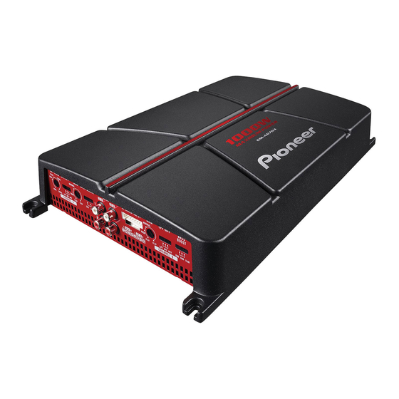
アンプ Pioneer GM-A4704のPDF オーナーズマニュアルをオンラインで閲覧またはダウンロードできます。Pioneer GM-A4704 19 ページ。 Bridgeable four-channel power amplifier
Pioneer GM-A4704 にも: オーナーズマニュアル (33 ページ)
- 1. Information to User
- 2. After-Sales Service for Pioneer Products
- 3. If You Experience Problems
- 4. Visit Our Website
- 5. The Safety of Your Ears Is in Your Hands
- 6. About Bridged Mode
- 7. Before Connecting the Amplifier
- 8. About Suitable Specification of Speaker
- 9. Connecting the Speakers
- 10. Connections When Using the RCA Input Jack
- 11. Connections When Using the Speaker Input Wire
- 12. Connecting the Power Terminal
- 13. Connecting the Speaker Output Terminals
- 14. Before Installing the Amplifier
- 15. Example of Installation on the Floor Mat or Chassis
- 16. Specifications
(Installation
)
•
Check all connections and systems before
final installation.
•
After installing the amplifier, confirm that the
spare tire, jack and tools can be easily re-
moved.[!]
Example of installation on
the floor mat or chassis
1
Place the amplifier in the desired instal-
lation location.
Insert the supplied tapping screws (4 mm x
18 mm (1/8
in.
x 3/4 in.)) into the screw holes
and push on the screws with a screwdriver so
they make an imprint where the installation
holes are to be located.
2
Drill 2.5 mm (1/8 in.) diameter holes at
the imprints either on the carpet or directly
on the chassis.
\.
3
Install the amplifier with the use of
supplied tapping screws (4 mm x 18 mm
(1/8 in. x 3/4 in.)).
CD
Tapping-screws (4 mm x 18 mm (1/8 in. x
3/4 in.))
(1)
Drill a 2.5 mm (1/8 in.) diameter hole.
®
Floor mat or chassis
G)
Hole-to-hole distance: 343 mm (13-1/2 in.)
(GM-A6704)
I
313 mm (12-3/8 in.) (GM-
A4704)
®
Hole-to-holed istance: 195 mm (7 -5/8 in.)
C!J
En
(Additional information )
Specifications
GM-A6704
Power source ............................. 14.4 V DC (1 0.8 V to 15.1 V
allowable)
Grounding system ................... Negative type
Current consumption ............ 31 A (at continuous power,
40)
Average current consumption
8.5 A (4 0 for four chan nels)
14 A (4 0 for two channels)
Fuse ................................................ 25 Ax 2
Dimensions (W x H x D) ... 356 mm x 60 mm x
215mm
(14 in. x 2-3/8 in. x 8-1/2 in.)
Weight .......................................... 2.2 kg (4.91bs)
(Leads for wiring not in-
cluded)
Maximum power output ....... 170 W x 4 (40)
I
250 W x 4
(2 0)
I
1000 W TOTAL
(BRIDGE)
Continuous power output ... 60W x 4 (at 14.4V, 40,
20Hz to
20kHz~
1 % TH D
+N)
190
w
x 2 (at 14.4 V, 4
o
BRIDGE 1
kHz,~
1% THO
+N)
95 W x 4 (at 14.4 V, 20,
1kHz,~
1% THD+N)
Load impedance ...................... 40 (20 to 80 allowable)
Frequency response ............... 10Hz to 70kHz ( +0 dB,
-3dB)
Signal-to-noise ratio ............... 95 dB (IHF-A network)
Distortion ..................................... 0.05% (1 0 W, 1 kHz)
Low pass fi Iter:
(Ach)
Cut off frequency ........... 80 Hz
Cut off slope ..................... -12 dB/oct
(Bch)
Cut off frequency ........... 80 Hz
Cut off slope ..................... -12 dB/oct
High pass filter:
(Ach)
Cut off frequency ........... 40Hz to 500Hz
Cut off slope ..................... -12 dB/oct
(Bch)
Cut off frequency ........... 80 Hz
Cut off slope ..................... -12 dB/oct
Bass boost:
Frequency
50 Hz
Level
0 dB/6 dB/12 dB
Gain control:
RCA ...................................... 0.3 V to 6.5 V
Speaker .............................. 3.0 V to 26 V
Maximum input level
I
impedance:
RCA ...................................... 6.5 VI 22 kO
Speaker .............................. 26 VI 16 kO