- ページ 11
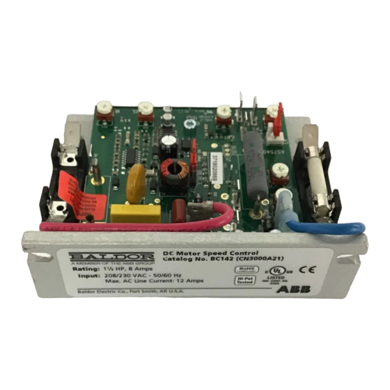
コントロールユニット ABB Baldor BC142-5のPDF インストレーション&オペレーティングマニュアルをオンラインで閲覧またはダウンロードできます。ABB Baldor BC142-5 20 ページ。 Dc control

Table 2-4 Plug-In Horsepower Resistor® & Armature Fuse Kit Selection
90 -130 VDC
180 VDC
Motors (HP)
Motors (HP)
1/100
1/50
1/50
1/25
1/30
1/15
1/20
1/10
1/15
1/8
1/12
1/6
1/8
1/4
1/6
1/3
1/4
1/2
1/3
3/4
1/2
1
3/4
1-1⁄2
1*
2*
1-1⁄2*
3*
* Indicates an Auxiliary Heat Sink (Catalog No. BC143, or equivalent) must be used.
Remote Main Speed Potentiometer Connection
The control is supplied with a Main Speed Potentiometer to control motor speed. Connect the low side
of the potentiometer to Terminal P1. Connect the wiper of the potentiometer to Terminal P2. Connect
the high side of the potentiometer to Terminal P3.
Voltage Following Connection
An isolated 0 - 9 Volt DC analog signal input can be used to control motor speed in lieu of the Main
Speed Potentiometer. The control output voltage will linearly follow the analog signal input. The signal
input must be isolated from the AC line. Connect the signal input positive lead (+) to Terminal P2 and
the negative lead (-) to Terminal P1. The source impedance of the signal input should be 10 kΩ or less.
The MAX Trimpot is not operational in voltage following mode. Set the MIN Trimpot, on the control, to
zero output (full counterclockwise rotation) and use auxiliary trimpots, if necessary, to scale and/or
limit the input voltage.
2-4
Approximate
Motor Current
(ADC)
0.2
0.3
0.33
0.5
0.8
0.85
1.3
2
2.5
3.3
5
7.5
10
15
Figure 2-3 Remote Main Speed Potentiometer Connection
Main Speed Potentiometer
(Front View)
Plug-In HP Resistor and
Armature Fuse Kit Cat.
No.
BR1000
BR0510
BR0350
BR0250
BR0251
BR0180
BR0100
BR0101
BR0050
BR0035
BR0025
BR0015
BR0010
BR0006
Terminal "P3"
P2
Terminal "P2"
P3
P1
Terminal "P1"
MAX
High
Wiper
Low
Plug-In HP
Armature Fuse
Resistor Value
Rating (Amps)
(Ω)
1
0.5
0.51
0.5
0.35
0.5
0.25
0.75
0.25
1
0.18
1.25
0.1
2
0.1
2.5
0.05
4
0.035
5
0.025
8
0.015
12
0.01
15
0.006
25
MN704
