- ページ 8
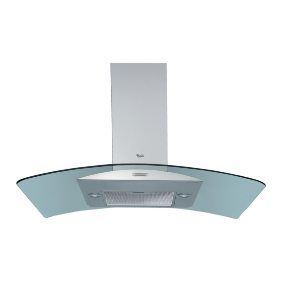
換気フード Whirlpool AKR 953のPDF 設置シートをオンラインで閲覧またはダウンロードできます。Whirlpool AKR 953 10 ページ。
Whirlpool AKR 953 にも: 設置シート (20 ページ)

INSTALLATION - ASSEMBLY INSTRUCTIONS
Preliminary information for installing the hood:
Expansion plugs are provided to secure the hood to most types of ceilings. A qualified technician is needed, however, to make
sure that the plugs are suitable for your ceiling. The ceiling must be strong enough to take the weight of the hood.
Disconnect the power supply at the home main switch during electrical connections.
1. Adjust extension of the hood support structure, as the final height of the hood depends on this, and remember that with
installation completed the hood must be at least 50 cm above the cooktop in case of electric cookers and 75 cm in case of
gas or mixed cookers.
2. Fix the two sections of the structure using 8 screws.
3. Place the ceiling hole diagram directly above the cook-top (the centre of the diagram must match the centre of the cook-
top and the edges must be parallel to the sides of the cook-top - the side of the diagram with the wording FRONT
corresponds to the control panel side). Prepare the electrical connection.
4. Drill as shown (6 holes for 6 wall plugs - 4 plugs for hooking), screw the 4 outer screws leaving a space of about 1 cm
between the screw head and the ceiling.
5. Fit an exhaust pipe inside the truss and connect it to the collar of the motor compartment (exhaust pipe and clamps are not
provided).
6. Hook the truss to the 4 screws (see step 4).
CAUTION! The side of the truss with connection box corresponds to the side of the control panel with hood assembled.
7. Tighten the 4 screws.
8. Insert and tighten another 2 screws in the remaining free holes for secure fixing.
9. Carry out the electrical connection to the mains power supply, only turn on the power supply with assembly completed.
10. Hook the hood to the truss, check for perfect hooking - to hook the hood to the truss partially screw 4 screws (also see
step 12).
11. Fixing the hood to the truss with two screws, will also facilitate centering the two parts.
12. Tighten the 4 screws fixing the truss to the hood.
13. For extractor operation (13A), connect the other end of the exhaust pipe to the home drain device.
For filter operation (13F), fit deflector F on the truss and fix it with 4 screws to the special bracket. Finally, connect the
exhaust pipe to the collar located on the deflector.
14. Fit the nuts with fixing hooks supplied inside the top and bottom sections of the flues at the rectangular slots. A total of 10
nuts must be fitted.
15. Join the two top sections of the flue to cover the truss so that one of the slots on the sections is situated on the same side
of the control panel and the other on the opposite side.
Screw the two sections with 4 screws (2 each side - see the plan diagram for joining the two sections).
16. Fix the top flue assembly to the truss, near the ceiling, with two screws (one each side).
17. Carry out electrical connection of control panel and bulbs.
18. Join the two bottom sections of the flue covering the truss using 6 screws (3 each side - also see the plan diagram for joining
the two sections).
19. Insert the bottom section of the flue in the special seat to completely cover the motor compartment and electrical
connection box, and fix the hood with two screws from the inside.
20. Apply the 2 tabs (supplied) to cover the fixing points of the bottom flue (CAUTION! THE BOTTOM FLUE TABS ARE THE
NARROWER AND SHALLOWER ONES).
The wider and deeper tabs are those used for the top flue, and must be cut to size.
21. Turn the mains power on again at the central electrical panel and check for correct hood operation.
82
PL
CZ SK
H
BG RO SL
HR GB
5019 318 33109
