- ページ 12
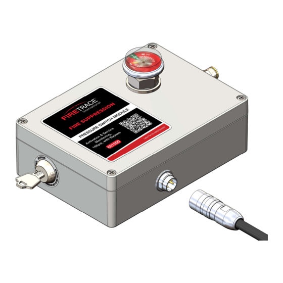
コントロールユニット FIRETRACE 800095-AのPDF インストレーション・マニュアルをオンラインで閲覧またはダウンロードできます。FIRETRACE 800095-A 18 ページ。 Dual pressure switch module with & without bypass

15
16
3.4 Closing the Module
3.4.1 With Bypass Switch
Reference Figure 6 in Section 3.1.1 above for part callouts
1.
Place lid on top of the box
2.
Partially screw cover screws (5) in place
3.
Lube bonded washer (3)
4.
Install bonded washer (3) over EOL (4) threads, seat to cover
5.
Thread retaining nut (2) to hand tight then screw one more full turn with wrench
6.
Tighten all four cover screws (5)
7.
Install gauge (1)
3.4.2 Standard (without Bypass)
Reference Figure 7 in Section 3.1.2 above for part callouts.
1.
Place lid on top of the box
2.
Tighten all four cover screws (1)
3.5 Mounting the Module
The Dual Pressure Switch Module can be mounted in several different ways using the M4 SS threaded inserts located on the back of the box (see
Figure 10 below). The module can be mounted threading directly to the inserts, attaching flanges to allow for the use of self-tapping screws, or by
attaching magnets to the box to secure the module in its mounting location. Tighten screws to hand tight to avoid stripping the threaded inserts away
from the box. Thread locker should be used in higher vibration environments.
If mounted in a vertical orientation, remove the nameplate from the module and apply the supplied nameplate so that the content is readable.
DIOM 800095-A
Bypass
Closed
Normal
Open
Bypass
Open
Normal
Open
Bypass
Open
Table 5 – Testing Reference | Standard
Module
PS1
Config #
(Unpressurized)
1
Closed
2
Closed
3
Open
4
Open
Figure 10 – Threaded Insert
Open
Open
Open
Closed
Closed
PS2
PS1
(Unpressurized)
(Pressurized)
Closed
Open
Open
Open
Open
Closed
Closed
Closed
8
Open
Closed
Closed
Closed
Closed
Closed
Closed
Open
Closed
Open
PS2
(Pressurized)
Open
Closed
Closed
Open
7/22/2022
