- ページ 6
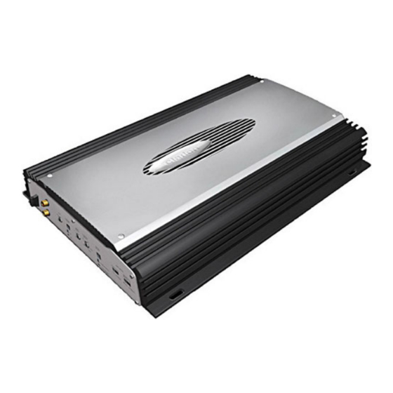
アンプ Clarion APA2001 APA2001 APA2001のPDF オーナーズ&インストレーション・マニュアルをオンラインで閲覧またはダウンロードできます。Clarion APA2001 APA2001 APA2001 17 ページ。 Mono amplifier
Clarion APA2001 APA2001 APA2001 にも: オーナーズ&インストレーション・マニュアル (8 ページ), サービスマニュアル (12 ページ)

- 1. Introduction
- 2. Table of Contents
- 3. Description
- 4. Installation, Mountinglwiring Precautions
- 5. Input Connections and Audio Control
- 6. Connections for Power and Speakers
- 7. Applications
- 8. Setting the Gain, Crossover/Bass Boost
- 9. Final System Checks, Troubleshooting
- 10. Product Specs
- 11. Warranty Information
clarion
APA250145012001
The Input Connections are gold-plated RCA Jacks. The Gain Controls provide a wide
adjustment range to accommodate output levels from any source unit brand.
• Gain Controls - Gain Controls allow you to set the nominal operating level of the
amplifier. The amplifiers range, 250mV to 2.5V for RCA inputs or 500mV to 5V for
speaker level inputs, can accommodate input levels from virtually any source unit
brand.
• Bass Boost Control - The amplifier also features a "high-Q" (i.e., narrow frequency
band) Bass Boost circuit.
It
acts much like an equalizer with a switchable gain fixed
at 45Hz. Use this feature to tune low-frequency audio response to compensate for a
less than ideal subwoofer enclosure design. The added boost produces rich, full bass
tones that are normally difficult to reproduce in the car audio environment. NOTE: If
Bass Boost is undesired, set Bass Boost to OFF.
High-PassILow-Pass Filter Controls
• Freq (Hz) Controls - The crossover frequency is fully adjustable between 50Hz and
250Hz. Use this feature, along with your speaker manufacturer's recommended
crossover frequencies, to quickly design a more advanced system. NOTE: If either of
the X-Over Mode Switches is set to OFF, varying the Freq (Hz) Control will produce
no effect.
• X-Over Mode Switches - These switches are equipped with 12dB per octave elec-
tronic filters for precise frequency attenuation with minimal phase distortion. Each
filter is activated by sliding the X-Over Mode Switch to either HP or LP (APA250
and APA2001 only).
• Speaker Level Inputs - These provide connections for a high-level stereo source.
These connections are provided for installations when the source unit does not have
RCA outputs.
WARNING:
When using the speaker (high-level) inputs, the Black wire must be grounded at the
radio. Failure to do so will result in noise and/or improper operation.
5
