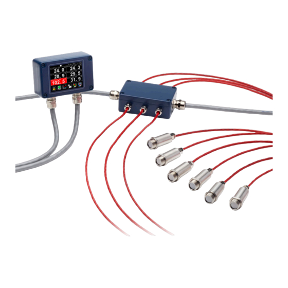
ELECTRICAL INSTALLATION
This diagram shows how to connect the sensors and output modules to a Modbus Master,
such as a Modbus PLC, SCADA system, Calex Panel PC or PM180 touch screen terminal.
Up to 247 slave devices, such as PyroMiniBus sensors and output modules, can be connected
to the same Modbus network.
SHIELDING
PyroMiniBus sensors use a shielded cable. The RS485 network bus cable and junction boxes
should also be shielded.
Avoid ground loops. Ensure there is only one path to ground from any point on the network
shielding.
Note: The sensing head metalwork forms part of the shield.
Ensure the PWR- wires of all sensors and GND of all output modules are connected to the
Signal Ground of the Modbus Master (or PWR- of the PM180 Modbus Master interface) and
the 0 V of the sensor power supply.
For more information on electrical connections to the PM180, including how to connect the
Modbus Slave interface, please see the PM180 section of this Operator's Guide.
IMPORTANT
Do not connect or disconnect Modbus devices with power on. Always disconnect power
before modifying electrical connections.
SENSOR WIRE COLOUR CODES:
WIRE COLOUR
Red
Black
White
Green
MODBUS OVER SERIAL LINE (RS485)
INTERFACE
Baud rate
Format
Reply delay
(ms)
6
9600
8 data, No parity, 1 stop
20
WIRE IDENTITY
PWR+
PWR-
RS+
RS-
SUPPORTED FUNCTIONS
Read register
Write single register
Write multiple register
0x03, 0x04
0x06
0x10
