- ページ 4
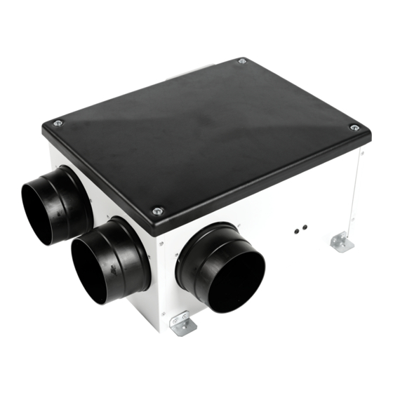
扇風機 aerauliqa QCmev 125のPDF インストレーション・マニュアルをオンラインで閲覧またはダウンロードできます。aerauliqa QCmev 125 16 ページ。 Whole house mechanical extract fan

• Ensure adequate air return into the room in compliance with existing regulations in order to ensure proper device operat
• If the environment in which the product is installed also houses a fuel-operating device (water heater, methane stove etc., that is not a "sealed
chamber" type), it is essential to ensure adequate air intake, to ensure good combustion and proper equipment operation.
• Install the product so that the impeller is not accessible from the air outlet side as verified by contact with the Test Finger (test probe "B" of the
norm EN61032) in compliance with the current safety regulations.
• Make sure there is enough space around the unit for maintenance.
OPERATION
Single speed operation
The unit runs at the speed set by turning the integral trimmer "V1" in the terminal box.
This is the default factory setting.
Wiring diagram: Fig.5A – Dip switch configuration: 0000 (Fig.5F)
Two speed operation
The unit runs continuously at the speed set by turning the integral trimmer "V1" in the terminal box and can be boosted at high speed, which is set
by turning the integral trimmer "V2" in the terminal box. Boost is activated, when needed, by means of a remote two-position switch (not supplied)
or by means of remote sensors (SEN-HY, SEN-CO2 or SEN-PIR), which are accessories on request.
Wiring diagram: Fig.5B – Dip switch configuration: 1000 (Fig.5F)
Variable speed operation with CTRL-M remote manual controller (accessory on request)
The unit runs at the speed set by turning the knob of the 149-SEN-CTRLM remote manual control panel (accessory, Fig.6).
Wiring diagram: Fig.5C – Dip switch configuration: 0100 (Fig.5F)
Variable speed operation through external domotic (BMS) system or ballast potentiometer
The unit runs at the speed set by turning the knob of an external 1-10V ballast potentiometer or set by an external 1-10V signal from a domotic
(BMS) system.
Wiring diagram: Fig.5D – Dip switch configuration: 0110 (Fig.5F)
Three speed operation with SEL-3V speed selector (accessory on request)
The unit runs at the speed selected by turning the knob of the SEL-3V speed selector (accessory, Fig.7).
Speed 1 is set by turning the integral trimmer "V1" in the terminal box.
Speed 2 is set by turning the integral trimmer "V2" in the terminal box.
Speed 3 is the maximum speed achievable by the unit.
Wiring diagram: Fig.5E – Dip switch configuration: 1000 (Fig.5F)
For humidistat version only (QCmev 80 HY - QCmev 125 HY)
Whatever is the chosen operation and the speed setting, when the humidity threshold is reached, the fan speed is increased by 15%.
When the humidity level returns below the threshold, the fan continues to run at increased speed for a pre-set period of time.
Humidity threshold is adjustable from 50% to 95% via trimmer HY (Fig.5G).
To deactivate the humidistat function, turn the trimmer HY completely clockwise (position G).
MAINTENANCE
Make sure the mains supply of the unit is disconnected before performing any maintenance.
The maintenance must be carried out by a qualified technician and in accordance with local rules and regulations.
STANDARD CONFORMITY
2014/35/EU Low Voltage Directive (LVD)
2014/30/EU Electromagnetic Compatibility (EMC),
in conformity with the following standards:
Electrical Safety
EN60335-1(2008); EN 60335-2-80(2005); EN 60335-2-80/A2(2009)
Electromagnetic Compatibility
EN 55014-1(2006)+A1+A2; EN 55014-2(1997)+A1(2001)+A2(2008)+IS1(2007)
EN 61000-3-2(2006)+A1(2009)+A2(2009); EN 61000-3-3(2008).
4
