- ページ 13
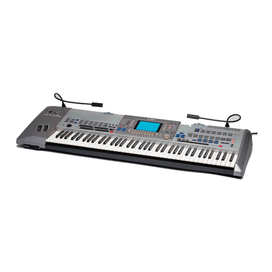
楽器 Yamaha 9000 ProのPDF サービスマニュアルをオンラインで閲覧またはダウンロードできます。Yamaha 9000 Pro 20 ページ。 Professional workstation
Yamaha 9000 Pro にも: オーナーズマニュアル (35 ページ)

[750A] x 6
AJACK2
PN4
[A]
[750H] x 18
• LDC Assembly
LCD
LCD Holder
[70C]: Bind Head Tapping Screw-B 3.0 X 6 MFZN2BL (EP600230)
(Fig. 8)
[750E] x 8
[750D] x 3
AJACK
[750C] x 4
PN3
PN2
EN
[750G] x 5
EN Circuit Board
[70B]: Bind Head Tapping Screw-B 3.0 X 6 MFZN2BL (EP600230)
[750]: Bind Head Tapping Screw-B 3.0 X 8 MFZN2BL (EP600190)
[760]: Bind Head Tapping Screw-B 3.0 X 6 MFZN2Y (EP600130)
[800]: Bonding Tapping Screw-B 3.0 X 8 MFZN2BL (VN413300)
[70C]
LCD Assembly
INV
DJACK
[70B] x 4
[800]
PN1
MV
[750J] x 4
[750F] x 17
[760]
(Fig. 7)
11.
Keyboard Assembly
(Time required: About 30 minutes)
11-1 Remove the bottom assembly. (See procedure 1.)
11-2 Remove the AM circuit board. (See procedure 2.)
11-3 Remove the power supply assembly. (See procedure
2.)
11-4 Remove the DA circuit board. (See procedure 3.)
11-5 Remove the DM and TG circuit boards. (See
procedure 4.)
11-6 Remove the four (4) screws marked [300B] and the
three (3) screws marked [310C]. The keyboard
assembly can then be removed with the center angle
bracket and the keyboard supports. (Fig. 9)
11-7 Remove the twelve (12) screws marked [320E]. The
center angle bracket and the three (3) keyboard
supports can then be removed from the keyboard
assembly. (Fig. 9)
11-8 Remove the five (5) screws marked [320F]. The key
slip can then be removed from the keyboard
assembly. (Fig. 9)
[750B] x 10
LED
[750I]
9000 Pro
13
