- ページ 2
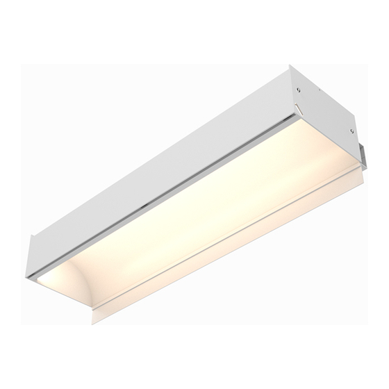
照明器具 CALI alumLEDs ALS500T-RMW-HCのPDF 取付説明書をオンラインで閲覧またはダウンロードできます。CALI alumLEDs ALS500T-RMW-HC 16 ページ。
CALI alumLEDs ALS500T-RMW-HC にも: 取付説明書 (16 ページ)

LINEAR CONFIGURATION
Standard Length
A
8'
19'6"
MITERED CONFIGURATION
Standard Length
A
8'
1'
Custom Length
B
Mitered Corner
D
JUMPER CONFIGURATION
Standard Length
A
Jumper Cable
8'
POWER DISTRIBUTION
Driver
F
To Power Source
Continuous Connection
To Power Source
Driver
F
CALIFORNIA ACCENT LIGHTING, INC.
2820 E. Gretta Lane, Anaheim, CA 92806
ph. 800.921.CALI (2254) | fx. 714.535.7902 | [email protected] | calilighting.com
© CALI. All rights reserved. CALI reserves the right to make changes or withdraw specifications without prior notice.
Custom Length
B
End Cap
8'
3'6"
Mitered Corner
D
6'
1'
8'
End Cap
C
End Cap
C
E
8'
Circuit #1
H
(Gray)
G
Circuit #2
H
(White)
ALS500T-RMW-HC
KEY
A
Standard Length: Luminaire runs are constructed in 8' segments.
Custom Length: Any required length that is not 8'. Typically the last
C
B
segment of a run.
C
End Cap: Used to terminate a run.
Mitered Corner: Standard 90° Mitered Corner. Custom angles available
D
upon request.
E
Jumper Cable: Used to connect two luminaires with a gap between.
Driver: The driver is typically mounted on top of the first luminaire
F
segment of a run. The driver may also be mounted elsewhere. Each run
typically has its own driver.
Continuous Connection: Each luminaire segment is built with quick
G
disconnects to easily connect to the next segment in line.
Circuits: Example U-Shaped run exceeds Max Run lengths and is split
H
into two circuits, each with their own driver. Max Run lengths vary by light
source. See light source specifications for details.
INSTALLATION INSTRUCTIONS
Design Guidelines (Configurations)
5 / 20 / 2021 / Rev 3
Page 2 of 16
