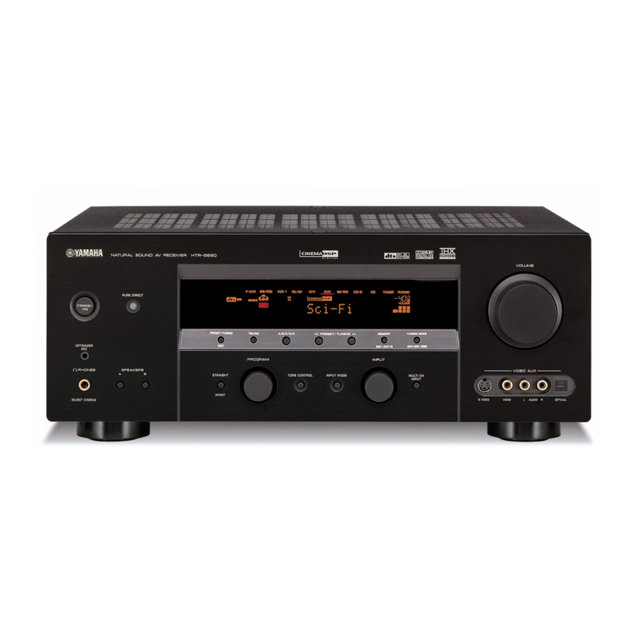
- 1. Table of Contents
- 2. Service Manual
- 3. Important Notice
- 4. To Service Personnel
- 5. Front Panel
- 6. Remote Control Panel
- 7. Rear Panels
- 8. Specifications
- 9. Internal View
- 10. Disassembly Procedures
- 11. Updating Firmware
- 12. Self Diagnosis Function (Diag)
- 13. Amp Adjustment
- 14. Display Data
- 15. IC Data
- 16. Remote Control
IC512: D601A002PYP180 (DSP P.C.B)
Decoder
No.
Name
I/O
Function
99
EA17
O/Z
For external memory, Address 17
100
EA19
O/Z
For external memory, Address 19
101
EA20
O/Z
For external memory, Address 20
102
/CE0
O/Z
For external memory area, Enable 0
103
/CE1
O/Z
For external memory area, Enable 1
104
CVDD
S
1.2V power supply
105
CVDD
S
1.2V power supply
106
VSS
GND
Ground
107
DVDD
S
3.3V power supply
108
/BE1
O/Z
For external memory, Byte Enable Control 1
109
EA21
O/Z
For external memory, Address 21
110
/BE0
O/Z
For external memory, Byte Enable Control 0
111
ED13
IOZ
For external memory, Data 13
112
ED15
IOZ
For external memory, Data 15
113
ED14
IOZ
For external memory, Data 14
114
DVDD
S
3.3V power supply
115
VSS
GND
Ground
116
CVDD
S
1.2V power supply
117
ED11
IOZ
For external memory, Data 11
118
ED12
IOZ
For external memory, Data 12
119
ED9
IOZ
For external memory, Data 9
120
ED10
IOZ
For external memory, Data 10
121
ED6
IOZ
For external memory, Data 6
122
ED7
IOZ
For external memory, Data 7
123
ED8
IOZ
For external memory, Data 8
124
CVDD
S
1.2V power supply
125
VSS
GND
Ground
126
DVDD
S
3.3V power supply
127
ED4
IOZ
For external memory, Data 4
128
ED5
IOZ
For external memory, Data 5
129
ED3
IOZ
For external memory, Data 3
130
ED2
IOZ
For external memory, Data 2
131
ED1
IOZ
For external memory, Data 1
132
ED0
IOZ
For external memory, Data 0
133
CVDD
S
1.2V power supply
134
VSS
GND
Ground
135
GP0[1]
IOZ
General purpose I/O0 port 1
136
BUSREQ
O/Z
For external memory, Bus request output
137
/HOLDA
O/Z
For external memory, Hold request approval to host
138
/HOLD
I
For external memory, Hold request from host
139
AFSR1
IOZ
McASP1 reception LRCLK
140
ACLKR1
IOZ
McASP1 reception BCLK
141
DVDD
S
3.3V power supply
142
VSS
GND
Ground
143
AXR1[0]
IOZ
McASP1 transmission/reception data 0
144
AXR1[1]
IOZ
McASP1 transmission/reception data 1
145
AXR1[2]
IOZ
McASP1 transmission/reception data 2
146
AXR18[3]
IOZ
McASP1 transmission/reception data 3
147
AXR1[4]
IOZ
McASP1 transmission/reception data 4
148
VSS
GND
Ground
149
CVDD
S
1.2V power supply
150
AXR1[5]
IOZ
McASP1 transmission/reception data 5
151
AXR1[6]
IOZ
McASP1 transmission/reception data 6
152
AXRO[8]/AXR1[7]
IOZ
McASP1 transmission/reception data 7
153
ACLKX1
IOZ
McASP1 transmission BCLK
154
AMUTE1
OZ
McASP1 MUTE output
155
AFSX1
IOZ
McASP1 transmission LRCLK
156
GP0[0]
IOZ
General purpose I/O0 port 0 (SPI ready signal output Active: H)
IC512: D601A002PYP180 (DSP P.C.B)
Decoder
No.
Name
I/O
Function
157
CVDD
S
1.2V power supply
158
VSS
GND
Ground
159
AHCLKX1
IOZ
General purpose I/O0 port 8
160
GP0[8]
IOZ
HPI data pin 8
161
AHCLKR1
IOZ
McASP1 reception MCLK
162
DVDD
S
3.3V power supply
163
VSS
GND
Ground
164
GP0[3]
IOZ
General purpose I/O0 port 3
165
GP0[9]
IOZ
General purpose I/O0 port 9
166
GP0[10]
IOZ
General purpose I/O0 port 10
167
GP0[11]
IOZ
General purpose I/O0 port 11
168
GP0[12]
IOZ
General purpose I/O0 port 12
169
CVDD
S
1.2V power supply
170
VSS
GND
Ground
171
CVDD
S
1.2V power supply
172
GP0[13]
IOZ
General purpose I/O0 port 13
173
GP0[14]
IOZ
General purpose I/O0 port 14
174
GP0[15]
IOZ
General purpose I/O0 port 15
175
NMI
I
Nonmaskable Interrupt ↑ edge
176
/RESET
I
Device reset
177
CVDD
S
1.2V power supply
178
OSCIN
I
X'tal input, Oscillation: 12 to 25MHz
179
OSCOUT
O
X'tal output
180
OSCVSS
GND
X'tal GND internal connection
181
OSCVDD
S
X'tal 1.2V power supply internal connection
182
VSS
GND
Ground
183
DVDD
S
3.3V power supply
184
CLKOUT3
O
Programmable clock output up to 32 division of PLL
185
EMU1
IOZ
JTAG emulation pin 1 (1kΩ PD when boundary scanning)
186
EMU0
IOZ
JTAG emulation pin 0 (1kΩ PD when boundary scanning)
187
TDO
O/Z
JTAG Data Out
188
DVDD
S
3.3V power supply
189
VSS
GND
Ground
190
CVDD
S
1.2V power supply
191
TDI
I
JTAG Data In
192
TMS
I
JTAG Mode Select
193
TCK
I
JTAG Clock
194
VSS
GND
Ground
195
CVDD
S
1.2V power supply
196
CVDD
S
1.2V power supply
197
/TRST
I
JTAG Reset
198
RSV2
O/Z
Reserved (unconnected)
199
PLLG
A
Analog GND for PLL
200
RSV0
A
Reserved (unconnected)
201
PLLV
A
Analog 1.2V power supply for PLL
202
PLLHV
A
Analog 3.3V power supply for PLL
203
RSV1
I
Reserved (unconnected)
204
CLKIN
I
Clock input
205
CLKMODE0
I
PLL input clock selection: Clkin or X'tal
206
DVDD
S
3.3V power supply
207
VSS
GND
Ground
208
CVDD
S
1.2V power supply
HTR-5890
37
