- ページ 4
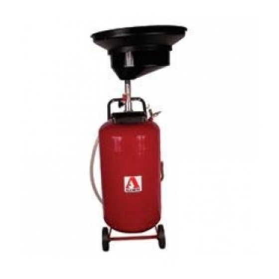
産業機器 Alemite 8587-1のPDF サービスマニュアルをオンラインで閲覧またはダウンロードできます。Alemite 8587-1 8 ページ。 Portable pressurized oil drain

SER 8587-1
Assembly
NOTE: See Page 2 for component iden-
tification on all procedures.
1. Install each Wheel (20) onto Tank (25).
• Install Washer (21) and Screw (22) that secures
each Wheel to the Tank.
• Tighten Screws (22) securely.
2. Position each Wheel Caster (30) onto the Tank.
3. Install Washer (32) and Acorn Nut (31) that
secures each Wheel Caster to the Tank.
• Tighten each Acorn Nut securely.
4. Install Handle (23) into the sockets on the Tank.
• Tighten Screws (37) securely.
5. Lubricate O-Rings (5) with clean oil.
6. Carefully position the Bowl and Swivel Stem
assembly into the Extension Tube and Swivel
Body assembly.
• Tighten Screw (8) securely.
7. Install Strainer (2) and Splash Guard (1) onto
Bowl (3).
8. Position Tool Tray (24) onto the Tank's bracket.
Modes of Operation
Collection
1. Make sure both ball valves are properly
positioned.
• See Figure 2.
Position Tube and Bowl Assembly
2. Loosen Hand Wheel (12).
3. Raise or lower the Tube and Bowl assembly to the
desired position.
4. Tighten the Hand Wheel.
IMPORTANT: Do not allow the tank to
fill above the highest mark on Level
Gauge (29). An excessive quantity of oil
may cause oil discharge at Air Connec-
tor (18).
Changes Since Last Printing
Part #s 393767-26 and 393767-27
(5-09)
Emptying
5. Remove Plug (27) from the nozzle on Delivery Hose
Assembly (26).
• Position the nozzle into an appropriate collection
container.
6. Make sure that Hand Wheel (12) is tight.
7. Make sure both ball valves are positioned properly.
• See Figure 2.
CAUTION
Do not exceed 7 psi (0.5 Bar) air pressure when emp-
tying this drain. Damage to components can occur.
8. Set the air supply to a maximum of 7 psi (0.5 Bar).
9. Attach air supply to Connector (18).
Figure 2 Ball Valve Positions for Modes of Operation
4
Portable Pressurized Oil Drain
Alemite, LLC
