- ページ 12
ソウ Clarke WOODWORKER CBS250のPDF 取扱説明書をオンラインで閲覧またはダウンロードできます。Clarke WOODWORKER CBS250 20 ページ。 45 mm (10”) bandsaw & stand
Clarke WOODWORKER CBS250 にも: 取扱説明書 (13 ページ)

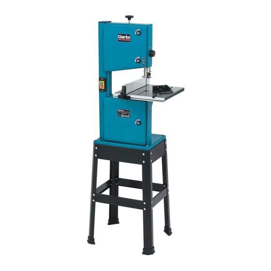
Changing the Sawblade.
Ensure the machine is switched OFF, and isolated from the
mains electrical supply.
•
Remove the rip fence and bevel gauge - 'A'.
•
Remove the width of cut indicator - 'B'.
•
Remove the table insert - 'C'.
•
Raise the upper guide block fully - 'D'
•
Open the upper and lower doors - 'E'.
•
Slacken the tension on the sawblade by turning the
handwheel on the top of the bandsaw 'F', in an
anticlockwise direction.
•
Carefully remove the sawblade, and store safely.
NOTE: The saw blade requires very careful handling to
avoid the possibility of personal injury.
•
Clean the machine, using a soft brush and vacuum
cleaner.
•
Fit the new sawblade in reverse order, ensuring it runs
in the correct direction i.e. with the teeth pointing
down at the front.
NOTE: before tensioning the blade, ensure it is located in
all the blade guides correctly.
•
Slowly tension the blade by turning the handwheel
on top of the machine in a clockwise direction.
Simultaneously, slowly rotate the upper blade wheel in a clockwise direction whilst
observing the blade. It should run in the centre of both blade wheels.
Tension the blade sufficiently to ensure it is taught and does not slip on the blade
wheels - do not overtighten.
If the blade runs off centre, adjust the tracking as follows.
Saw Blade Tracking
Before carrying out this adjustment, all six blade guides must first be backed off, 3 above
and 3 below the table - see page 14 for blade guide adjustments.
It will also be necessary to remove the table insert.
•
Open the upper and lower doors
•
Release the handwheel lock, located at the rear of the upper
wheel housing (see Fig. 14), by turning it anticlockwise.
•
Whilst slowly rotating the upper blade wheel clockwise, slowly
turn the hand wheel at the rear of the machine, (see Fig. 14),
observing the reaction of the sawblade. If it tracks in the desired
direction, continue to turn the handwheel until the blade runs
in the centre of the blade wheels, if the blade tracks in the
wrong direction, turn the handwheel in opposite direction.
When satisfied,re tighten the handwheel lock
12
F
Fig.13
D
E
C
A
A
B
E
Fig.14
Handwheel
Lock
